Rotary bearing mechanism and engine split assembly tray

A technology of carrying mechanism and carrying plate, which is applied in the direction of packaging, transportation and packaging, rigid containers, etc., can solve the problems of reducing production efficiency, increasing labor costs, and difficult operations for operators, so as to avoid overturning, prevent tilting, and optimize rotation stability sexual effect

Inactive Publication Date: 2021-04-09
DONGFENG MOTOR CORP HUBEI
View PDF3 Cites 1 Cited by
  • Summary
  • Abstract
  • Description
  • Claims
  • Application Information

AI Technical Summary

Problems solved by technology

[0004] Since the engine and gearbox support brackets and the pallet base are fixed by welding, the layers cannot be rotated or changed in direction, so that the sub-package operation must be completed by at least two people on both sides of the sub-package pallet, thus increasing the Labor costs, and a large operating space needs to be reserved, which increases the floor space of the entire production line
In addition, part of the assembly position cannot be changed due to the angle of the pallet, which makes it difficult for the operator to work, thereby reducing production efficiency

Method used


Image

  • Rotary bearing mechanism and engine split assembly tray
  • Rotary bearing mechanism and engine split assembly tray
  • Rotary bearing mechanism and engine split assembly tray

Examples


Embodiment 1

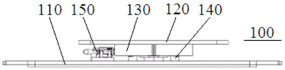
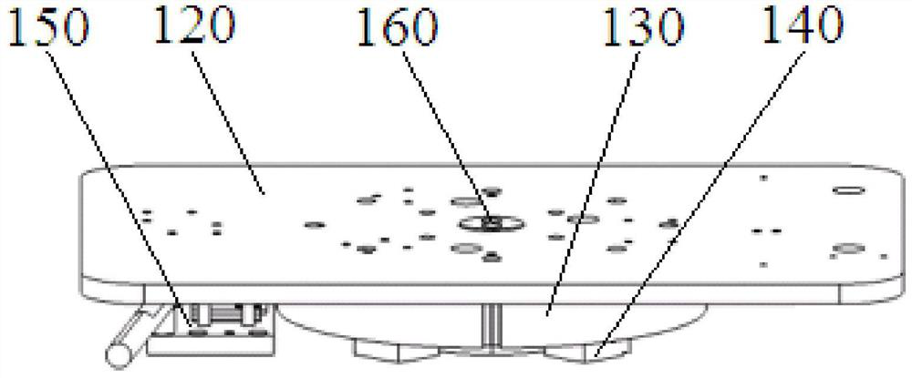
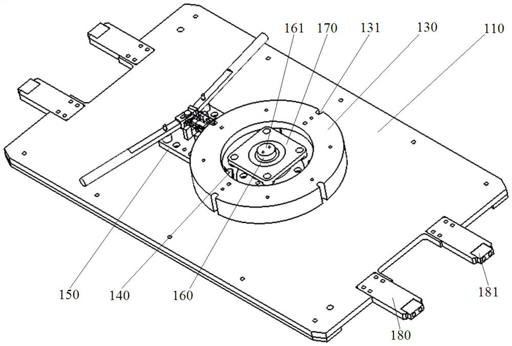
[0043] An embodiment of the present invention provides a rotating bearing mechanism 100, the structure of which is as follows Figure 1 to Figure 3 As shown, it specifically includes a tray base 110, a rotating shaft 160, a bearing plate 120, a rotating bearing plate 130 and more than three load bearing components 140. The tray base 110, load bearing components 140, rotating bearing plate 130 and bearing plate 120 Arranged sequentially from bottom to top to form a multi-layer bearing structure, the rotating shaft 160 is rotationally connected to the tray base 110 or the loading plate 120, and the rotating loading plate 130 is fixedly connected to the loading plate 120, and the rotating shaft 160 connects the loading plate 120, the tray base 110 to the The rotating bearing plate 130 is connected as a bearing body to realize the functions of load-bearing and stably supporting the engine and the transmission. The rotating bearing plate 130 is set on a plurality of load-bearing co...

Embodiment 2

[0057] Based on the same inventive concept, this embodiment provides an engine sub-package tray, its structure is as follows Figure 8 with Figure 9 As shown, the rotary bearing mechanism 100 including the engine support assembly, the transmission support base 230 and the above-mentioned embodiment 1, the engine support assembly and the transmission support base 230 are installed on the bearing plate 120 of the rotation bearing mechanism 100, the specific details of the rotation bearing mechanism 100 Refer to Embodiment 1 for the structure, and details are not repeated here.

[0058] see Figure 8 with Figure 11 , in this embodiment, the engine support assembly includes an engine support base 220 and an engine support module 210, the engine support base 220 is installed on the carrier plate 120 through a support column 250, and the engine support module 210 is detachably installed on the engine support base 220, The engine support module 210 is special-purpose. The size o...


PUM


Abstract

The invention discloses a rotary bearing mechanism and an engine split assembly tray. The rotary bearing mechanism comprises a tray base, a rotating shaft, a bearing plate, a rotary bearing disc and three bearing stress assemblies or more, wherein the tray base, the bearing stress assemblies, the rotary bearing disc and the bearing plate are sequentially arranged from bottom to top to form a multi-layer bearing structure, the rotating shaft is rotatably connected with the tray base or the bearing plate, the rotary bearing disc is fixedly connected with the bearing plate, the bearing plate, the tray base and the rotary bearing disc are connected into a bearing body through the rotating shaft, and the effects of bearing loads and stably bearing an engine and a transmission are achieved. The rotary bearing disc is arranged on the multiple bearing stress assemblies in a sleeving mode, so that the rotary bearing mechanism has better rotating stability. According to the rotary bearing mechanism, through cooperation of the rotary bearing disc and the multiple bearing stress assemblies, the technical effects that the bearing plate is prevented from inclining, and the whole rotary bearing mechanism is prevented from overturning or the engine and the transmission are prevented from sliding down can be achieved.

Description

technical field [0001] The application belongs to the technical field of automobile assembly tooling, and in particular relates to a rotating bearing mechanism and an engine subassembly tray. Background technique [0002] The sub-assembly of the engine and transmission is a necessary process of the automobile engine sub-assembly line. During the sub-assembly, the engine and transmission must be placed on the sub-package tray according to the vehicle type classification, so that the sub-assembly line operators can carry out the assembly work. [0003] Generally, the tray is a fixed structure formed by welding, and the support bracket matching the shape of the engine and the transmission is directly welded on the tray base, and the support bracket and the tray become a whole. [0004] Since the engine and gearbox support brackets and the pallet base are fixed by welding, the layers cannot be rotated or changed in direction, so that the sub-package operation must be completed b...

Claims


Application Information

Patent Timeline
Patent Type & Authority Applications(China)
IPC IPC(8): B65D19/38B65D19/40
CPCB65D19/38B65D19/40
Inventor 秦红英文国伟钱军叶芹周洲
Owner DONGFENG MOTOR CORP HUBEI
Why Eureka
Try Eureka