Tiny dust treatment device for cotton yarn processing
A processing device and micro-dust technology, which is applied in the field of cotton yarn processing, can solve the problems of incomplete cleaning of micro-dust and low production efficiency, and achieve the effects of sufficient dust removal, improved quality, and improved work efficiency
- Summary
- Abstract
- Description
- Claims
- Application Information
AI Technical Summary
Problems solved by technology
Method used
Image


Examples
Embodiment 1
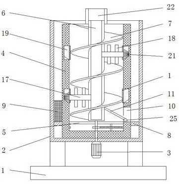
[0025] Embodiment 1, with reference to Figure 1-5 , a kind of fine dust processing device for cotton yarn processing, comprising a base 1, the top of the base 1 is welded with a casing 2, and the bottom of the casing 2 is equipped with a servo motor 3, and the inner wall of the bottom of the casing 2 is rotatably connected with an inner tank 4, and the inner wall A clapboard 5 is welded between the inner walls around the bottom of the liner 4, the output shaft of the servo motor 3 runs through the clapboard 5 and is welded with a support tube 6, and the outer wall of the support tube 6 is welded with a spiral blade 7, and the outer wall of the bottom of the liner 4 is connected to the A retaining ring 8 is rotatably connected between the inner walls of the shell 2, and a scraper 9 is welded on the outer wall of the liner 4 above the retaining ring 8, and a first discharge port 10 is opened through the outer wall of one side of the inner liner 4, and the second A deflector 11 ...
Embodiment 2
[0026] Embodiment 2, with reference to Figure 1-3 and Figure 6-7 , a kind of fine dust treatment device for cotton yarn processing, comprising a servo motor 2, the output shaft of the servo motor 3 is fixedly connected to the outer wall between the partition 5 and the bottom of the inner tank 4 with a driving gear 14, and the partition 5 and the inner tank The connecting gear 15 is rotatably connected between the inner walls of the bottom of 4, the inner wall of the bottom of the liner 4 is welded with a driven gear ring 16, and the outer walls of both sides of the support tube 6 are connected with staggered connecting pipes 17 through the rotation, and the connecting pipes Stirring tubes 18 are welded through the inner wall around 17, and fixed grooves 19 are opened at the position of the connecting pipe 17 in the liner 4, and bevel gear rings 20 are installed on the inner walls of the bottom of the fixing grooves 19, and the bevel gear rings The top of 20 is meshed with a...
PUM
 Abstract
Description
Claims
Application Information