Assembly type steel structure assembly process

A steel structure and assembly technology, which is applied in the direction of building construction, construction, and building material processing, can solve problems that affect the stability and earthquake resistance of steel structures, improper welding seam processing, and unstable structural assembly.

Inactive Publication Date: 2021-04-09
倪雨阳
View PDF0 Cites 0 Cited by
  • Summary
  • Abstract
  • Description
  • Claims
  • Application Information

AI Technical Summary

Problems solved by technology

However, most of the connection nodes of the fabricated steel structure are connected by bolt welding, and the unreasonable design may easily lead to unstable assembly of the structure, and the on-site weld is the main part of the steel structure that is prone to corrosion. Therefore, a prefabricated steel structure assembly process is proposed. The assembled steel beam column and steel plate are assembled into a complete steel structure building by means of bolt clamping
[0003] During the assembly process of the fabricated steel structure, according to the characteristics of the connection nodes, it is necessary to assemble and lock the steel structure beam column and the steel structure plate together: the existing assembled steel structure assembly equipment has the following defects: 1. The existing assembly Most of the steel column connection nodes of the steel structure assembly equipment are welded and locked, which leads to corrosion and corrosion due to improper treatment of the welds, which affects the service life of the steel structure building; 2. The existing assembly steel structure assembly equipment cannot The adjustment of the support angle affects the support strength of the steel structure building, which in turn affects the stability and earthquake resistance of the steel structure building

Method used


Image

  • Assembly type steel structure assembly process
  • Assembly type steel structure assembly process
  • Assembly type steel structure assembly process

Examples


Embodiment Construction

[0029] The specific embodiment of the present invention will be described in further detail by describing the embodiments below with reference to the accompanying drawings, the purpose is to help those skilled in the art to have a more complete, accurate and in-depth understanding of the concept and technical solutions of the present invention, and To facilitate its practice, but not as a limitation of the invention.

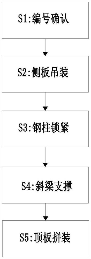
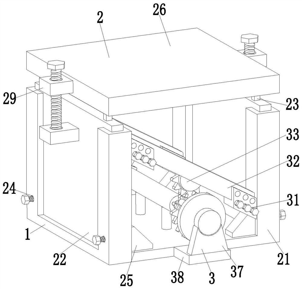
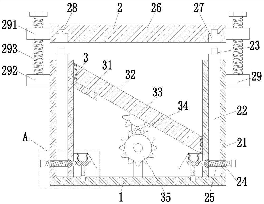
[0030] See attached Figure 1-6 As shown, a prefabricated steel structure assembling process uses a prefabricated steel structure assembling equipment. The prefabricated steel structure assembling equipment includes an assembling base plate 1, a locking device 2 and an angle adjusting device 3. The assembling Locking devices 2 are installed symmetrically at both ends of the bottom plate 1 , and an angle adjustment device 3 is arranged between the two locking devices 2 , and the angle adjustment device 3 is installed in the middle of the upper end surface of the ...


PUM


Abstract

The invention relates to an assembly type steel structure assembly process. Assembly type steel structure assembly equipment is used in the assembly type steel structure assembly process. The assembly type steel structure assembly equipment comprises an assembly bottom plate, locking devices and an angle adjusting device, wherein the locking devices are symmetrically mounted at the two ends of the assembly bottom plate; and the angle adjusting device is arranged between the two locking devices and mounted in the middle of the upper end face of the assembly bottom plate. The problems that most of steel column connecting joints of existing assembly type steel structure assembly equipment adopt a welding locking mode, consequently, corrosion is prone to occurring due to improper weld joint treatment, and the service life of a steel structure building is affected can be solved, and meanwhile the problems that the supporting angle of a beam cannot be adjusted through the existing assembly type steel structure assembly equipment, the supporting strength of the steel structure building is affected, and then the stability and shock resistance of the steel structure building are affected can be solved.

Description

technical field [0001] The invention relates to the technical field of steel structure assembly, and specifically proposes an assembled steel structure assembly process. Background technique [0002] Assembled building with steel-structure refers to an assembled building whose structural system is composed of steel (structure) parts. The prefabricated building refers to the transfer of a large number of on-site operations in the traditional construction method to the factory, where the building components and accessories (such as floor slabs, wall panels, stairs, balconies) are processed and manufactured in the factory, and transported to the construction site. A building that is assembled and installed on site through reliable connections. Prefabricated buildings can be divided into prefabricated concrete buildings and prefabricated steel structure buildings according to the different materials used. Compared with prefabricated concrete buildings, prefabricated steel stru...

Claims


Application Information

Patent Timeline
IPC IPC(8): E04G21/14E04G21/16E04B1/24E04B1/58
CPCE04B1/2403E04B1/58E04B2001/2406E04G21/14E04G21/162
Inventor 倪雨阳顾元帅
Owner 倪雨阳
Why Eureka
Try Eureka