Zipper roller shutter structure

A rolling shutter structure and zipper technology, which is applied to building components, building structures, door/window protection devices, etc., can solve the problems that the skylight cannot be used for horizontal operation, the curtain wall structure cannot be used, and the curtain is easy to wrinkle and damage.

Active Publication Date: 2021-04-09
亨特道格拉斯窗饰产品(中国)有限公司
View PDF9 Cites 0 Cited by
  • Summary
  • Abstract
  • Description
  • Claims
  • Application Information

AI Technical Summary

Problems solved by technology

[0003] However, the ordinary zipper roller blind structure can only be used for vertical lifting, that is, relying on the weight of the bottom bar at the bottom of the curtain to realize the rising and falling of the roller blind, but it cannot be used for the horizontal operation of the lighting roof, and it cannot be opened from bottom to top, so it cannot be used In the curtain wall structure with a large inclination angle, it cannot run horizontally, left and right, etc., which greatly limits the application range of this type of product
[0004] At the same time, because the zippers are welded on both sides of the curtain, the two sides are thicker, and the curtain cannot be completely flattened only by the weight of the bottom rod. Therefore, the current structure of the zipper roller blind cannot be made too wide or too high, otherwise the curtain is prone to wrinkles. Especially in the process of raising the curtain, the curtain is extremely easy to wrinkle and damage

Method used


Image

  • Zipper roller shutter structure
  • Zipper roller shutter structure
  • Zipper roller shutter structure

Examples


Embodiment Construction

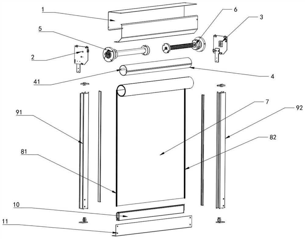
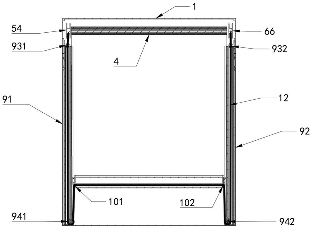
[0021] Depend on figure 1 As shown, the zipper roller blind structure of the present invention includes a casing 1 composed of a "7"-shaped upper casing and an "L"-shaped lower casing that cooperate with each other. The left and right ends of the casing 1 are respectively fixedly connected with a left mounting plate 2 and a right mounting plate 3. The casing 1 is provided with a reel 4 .

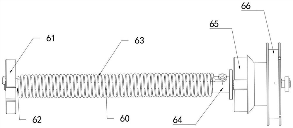
[0022] Reel 4 is provided with motor assembly 5, torsion spring assembly 6, and motor assembly 5 is inserted in the reel 4 from the left end of reel 4, and torsion spring assembly 6 is inserted in the reel 4 from the right end of reel 4.

[0023] The inner wall of the drum 4 has axially extending ribs 41 . The outer wall of the reel 4 is wound with a cord 7. The left and right edges of the cord 7 are respectively welded with a left slide fastener 81 and a right slide fastener 82. The left and right sides of the cord 7 are respectively provided with a left rail assembly 91 and a right rai...


PUM


Abstract

The invention relates to a zipper roller shutter structure. The structure comprises a winding drum, a left mounting plate and a right mounting plate are arranged on the two sides of the winding drum, a tubular motor and a torsional spring assembly are arranged in the winding drum, curtain cloth is wound on the outer wall of the winding drum, side rail assemblies are arranged on the left side and the right side of cord fabric, a bottom rod is fixed to the bottom end of the cord fabric, the torsional spring assembly comprises a transmission rod, a torsional spring rotating wheel, a torsional spring, a torsional spring fixed wheel and a first winding wheel, the torsional spring rotating wheel is connected with a transmission rod bearing and connected with the inner wall of the winding drum, the torsional spring fixed wheel is fixedly connected with the transmission rod, the two ends of the torsional spring are connected with the torsional spring fixed wheel and the torsional spring rotating wheel respectively, a second rolling wheel fixedly connected with the motor is arranged at the left end of the motor, a circulation rope is arranged between the first rolling wheel and the second rolling wheel, the right end of the circulation rope is fixed to the first rolling wheel, and the left end of the circulation rope sequentially penetrates through the right side rail assembly, the bottom rod and the left side rail assembly and then is fixed to the second rolling wheel.

Description

technical field [0001] The invention relates to the technical field of roller blinds, in particular to a zipper roller blind structure. Background technique [0002] The electric windproof zipper roller shutter machine is a motorized roller shutter mechanism that uses a tubular motor as power. It is easy to operate and quiet in work, and is widely used in stores, shopping malls, garages and other places. [0003] However, the ordinary zipper roller blind structure can only be used for vertical lifting, that is, relying on the weight of the bottom bar at the bottom of the curtain to realize the rising and falling of the roller blind, but it cannot be used for the horizontal operation of the lighting roof, and it cannot be opened from bottom to top, so it cannot be used In the curtain wall structure with a large inclination angle, it cannot run horizontally, left and right, etc., which greatly limits the application range of this type of product. [0004] At the same time, be...

Claims


Application Information

Patent Timeline
Patent Type & Authority Applications(China)
IPC IPC(8): E06B9/40E06B9/42E06B9/70E06B9/56E06B9/58
CPCE06B9/40E06B9/42E06B9/70E06B9/56E06B9/58
Inventor 瞿春辉
Owner 亨特道格拉斯窗饰产品(中国)有限公司
Why Eureka
Try Eureka