Ejector

A technology of ejectors and nozzles, applied in the field of ejectors, can solve the problems of low pressurization effect of ejectors, achieve the effect of submitting ejection efficiency, ensuring ejection effect, and simple structure

Active Publication Date: 2021-04-09
CHINA PETROLEUM & CHEM CORP +1
8 Cites 0 Cited by

AI-Extracted Technical Summary

Problems solved by technology

However, in the prior art, when there is a gas-liquid two-phase in the injection process of the wellhead...

Abstract

The invention provides an ejector. The ejector comprises an ejection gas fluid inlet, an ejected gas fluid inlet, an ejection nozzle, a contraction cavity, a throat pipe and a diffuser pipe, wherein the ejection gas fluid inlet is connected with the ejection nozzle, and the end, away from the ejection gas fluid inlet, of the ejection nozzle is connected with the contraction cavity; the ejected gas fluid inlet is connected with the contraction cavity; and the two ends of the throat pipe are connected with the contraction cavity and the diffuser pipe respectively; the nozzle is of a necking structure. The ejector can increase the flow speed of fluid passing through the nozzle in the ejection process and reduce pressure loss, thereby improving ejection efficiency.

Application Domain

Jet pumpsFluid removal +1

Technology Topic

EngineeringLaryngeal tube +2

Image

  • Ejector
  • Ejector

Examples

  • Experimental program(1)

Example Embodiment

[0030] The present invention will be further described in detail below in conjunction with the accompanying drawings and specific embodiments, but the protection scope of the present invention is not limited thereby.
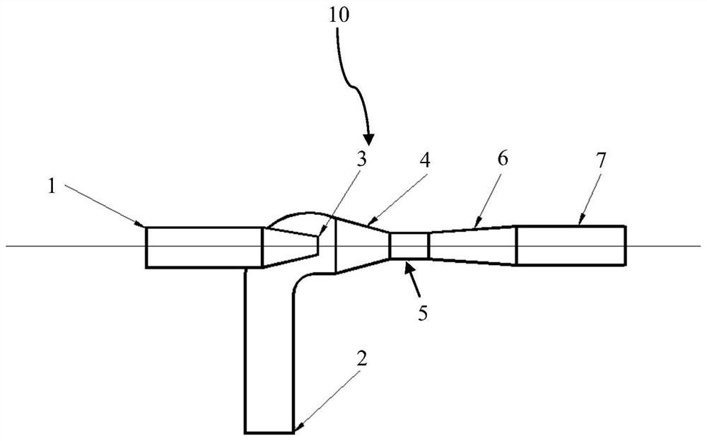
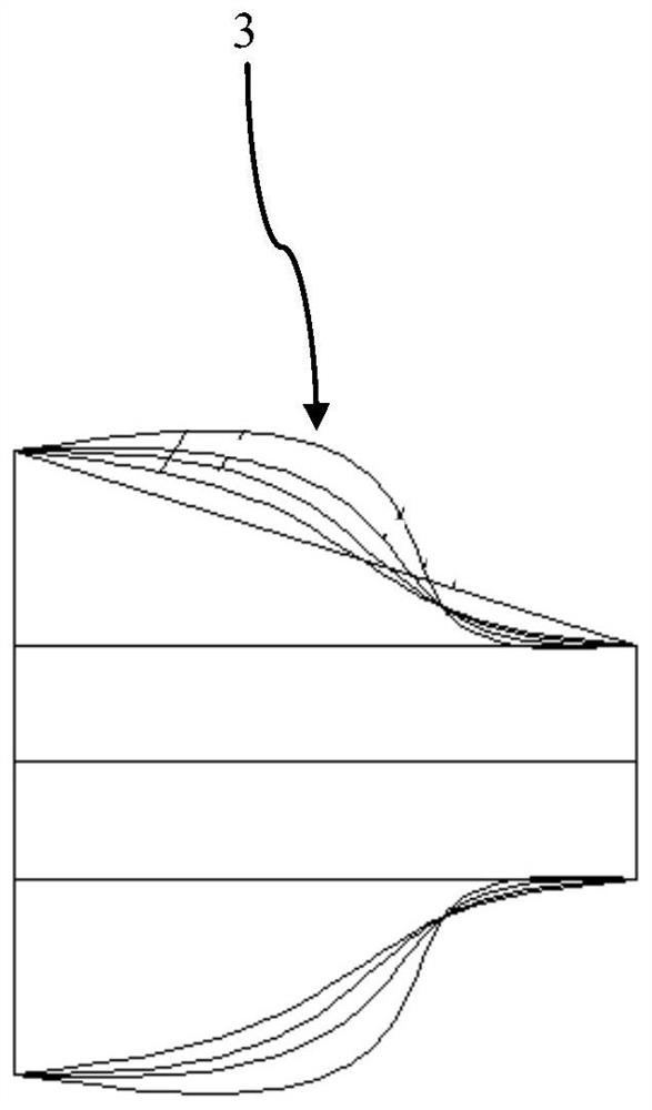
[0031] figure 1 The overall structure of the ejector 10 according to the embodiment of the present invention is schematically shown. figure 2 Schematically shows different structures of the injection nozzle 3 of the embodiment of the present invention.
[0032] like figure 1 As shown, the ejector 10 of the embodiment of the present invention includes an ejecting gas fluid inlet 1 , an ejected gas fluid inlet 2 , an ejecting nozzle 3 , a contraction cavity 4 , a throat 5 and a diffuser 6 . Wherein, the ejection gas fluid inlet 1 is connected to the ejection nozzle 3 , and the end of the ejection nozzle 3 away from the ejection gas fluid inlet 1 is connected to the contraction cavity 4 . The inlet 2 of the ejected gas fluid is connected with the constriction chamber 4 . Both ends of the throat pipe 5 are respectively connected with the constriction chamber 4 and the diffuser pipe 6 . The injection nozzle is a necked structure.
[0033] According to the ejector of the embodiment of the present invention, the high-pressure gas source is introduced through the fluid inlet of the ejector, and the pressure of the high-pressure gas source can be effectively used. The intake air is mixed to achieve the purpose of fully releasing the pressure and boosting the ejected airflow step by step. Specifically, the high-pressure liquid-containing gas is ejected at a certain speed after passing through the nozzle, and a low-pressure cavity is formed in the shrinkage cavity under the action of the jet, and the low-pressure fluid is sucked in through the inlet of the injected gas fluid under the action of turbulent diffusion and entrainment, and the two streams Fluids of different pressures exchange momentum, mass and energy in the throat and constriction tubes. The speed of the working fluid decreases through the diffuser tube, and the pressure gradually increases. It is output through the drainage tube to achieve the purpose of mixing and boosting. In addition, since the injection nozzle adopts a necked structure, it can further ensure that the gas flow is fully mixed under different gas-water ratio conditions, and can make full use of the expansion energy after gas compression and increase the speed of the mixed fluid to improve the injection efficiency.
[0034] like figure 2 As shown, in the injector 10 of the embodiment of the present invention, in a preferred implementation manner, the constriction structure is an oblique line. The constricted neck structure of the slash structure has a simple structure, is convenient to process and manufacture, and can ensure the ejection effect. Further, in another preferred embodiment, the constricted structure is a smooth tapering curve. The necking structure with a smooth tapering curve can increase the flow velocity at the outlet of the nozzle and improve the ejection effect. Specifically, in a preferred embodiment, the parameters of the tapering curve are defined by the equation (0~0.8) L:Y=a 1 *X 4 -a 2 *X 3 +a 3 *X 2 -a 4 *X+a 5 and (0.8~1)L:Y=a 1 *0.8 4 -a 2 *0.8 3 +a 3 *0.8 2 -a 4 *0.8+a 5 Sure. Among them, L is the length of the injection nozzle, Y is the diameter of the tapered curve, X is the distance from the projected nozzle surface onto the axis point to the nozzle outlet, and the parameter a 1 、a 2 、a 3 、a 4 , and a 5 is a constant determined according to different gas-liquid ratios. Designing the nozzle through the above equation can improve the distribution of the gas ejection flow velocity, thereby improving the outlet flow velocity and the size of the negative pressure area, and improving the ejection effect of the ejector. When the necking structure is an oblique line, in the above equation, a 1 、a 2 , a3 are all 0.
[0035] Preferably, in this embodiment, in order to meet the high-pressure gas source 10MPa, the gas-liquid ratio is 10000m 3 /m3 , Low pressure 4MPa, gas-liquid ratio 10000m 3 /m 3 , The necking structure of the injection nozzle is optimized under the condition of the outlet pressure of 4-5.5MPa. The necking curve is determined by the above equation, and the gas-liquid ratio in the fluid of the reference ejector is determined: when the gas-liquid ratio GLR≥5000m 3 /m 3 when a 1 is 5.2691, a 2 is 7.3561, a 3 is 1.7164, a 4 is 0.1069, a 5 It is 0.9977; when the gas-liquid ratio GLR<5000m 3 /m 3 when a 1 is 3.1751, a 2 is 4.0031, a 3 is 0.4914, a 4 is 0.1864, a 5 is 0.9973.
[0036] Further, as figure 1 As shown, in this embodiment, the diffuser pipe 6 has an involute structure. The diffuser in this structural form can further ensure the purpose of effectively reducing the velocity of the working fluid and mixing and boosting, thereby improving the ejection efficiency. Preferably, in this embodiment, the involute structure changes in non-equal tilt angles. The involute structure with non-equal inclination changes can make full use of the principle of fluid dynamics to maximize the average flow velocity of the nozzle.
[0037] Specifically, in this embodiment, the angle of the involute structure gradually increases from 3 degrees to 3 degrees to 15 degrees, and the inclination angle increase range is determined according to the gas-liquid ratio. The variation range of this angle variation can effectively guarantee the ejection effect. Preferably, in this embodiment, the inclination angle of the involute structure increases by 1 degree every 2 cm. This size setting form can effectively satisfy the angle variation range of the involute, thereby effectively ensuring the ejection effect.
[0038] like figure 1 As shown, further, in this embodiment, the ejector 10 further includes a drainage tube 7 , and one end of the drainage tube 7 is connected to the diffuser tube 6 . By setting the drainage pipe, it can ensure that the pressurized fluid can smoothly enter the gas field gathering and transportation pipeline network for export.
[0039] According to the above embodiments, it can be seen that the ejector of the present invention can increase the flow rate through the nozzle and reduce the pressure loss during the ejection process, thereby improving the ejection efficiency.
[0040] While the invention has been described with reference to a preferred embodiment, various modifications may be made and equivalents may be substituted for parts thereof without departing from the scope of the invention. In particular, as long as there is no structural conflict, the technical features mentioned in the various embodiments can be combined in any manner. The present invention is not limited to the specific embodiments disclosed herein, but includes all technical solutions falling within the scope of the claims.

PUM

no PUM

Description & Claims & Application Information

We can also present the details of the Description, Claims and Application information to help users get a comprehensive understanding of the technical details of the patent, such as background art, summary of invention, brief description of drawings, description of embodiments, and other original content. On the other hand, users can also determine the specific scope of protection of the technology through the list of claims; as well as understand the changes in the life cycle of the technology with the presentation of the patent timeline. Login to view more.

Similar technology patents

Photoelectric sensor for position of sun

InactiveCN101650173AEffective tracking range expandedSimple structure
Owner:WUHAN UNIV OF TECH

Magnetic cooling apparatus and control method thereof

ActiveUS20130180263A1simple structure
Owner:SAMSUNG ELECTRONICS CO LTD

Dual-Drivetrain of Power-Assist Vehicle

InactiveUS20100181130A1enhance uphill momentumsimple structure
Owner:CHOU WEN CHENG

Classification and recommendation of technical efficacy words

Why Eureka
Try Eureka