A hydraulic oil cylinder with high buffer performance and its working method

A hydraulic cylinder and hydraulic oil technology, applied in the field of hydraulic cylinders, can solve problems such as poor buffering effect, reduce the running speed of the piston rod, and single buffering method, and achieve the effects of improving service life, high-pressure shock resistance, and reducing damage

Active Publication Date: 2022-07-01
扬州市正浩液压机械设备有限公司
View PDF7 Cites 0 Cited by
  • Summary
  • Abstract
  • Description
  • Claims
  • Application Information

AI Technical Summary

Problems solved by technology

[0003] The object of the present invention is to provide a hydraulic oil cylinder with high cushioning performance and its working method to solve the following technical problems: the operating speed of the piston rod is reduced by changing the injection speed of the hydraulic oil through the first regulating valve and the second regulating valve, The cushioning effect is achieved from the outside of the cylinder. The arc-shaped insert plate at the end of the piston and the arc-shaped hole at the bottom of the end cover cooperate with the first buffer spring to buffer the speed when the piston rod is pushed out. The buffer plug at the other end of the piston cooperates with the buffer cover The sliding cover in the buffer cavity and the second buffer spring buffer the speed of the piston rod after retraction, and then achieve the buffer effect from the inside of the cylinder. The multiple buffer effects realize the buffer braking of the high-speed hydraulic cylinder, which is resistant to high-pressure shock and will not affect The reliability of the seal greatly improves the service life of the high-speed hydraulic cylinder, and the two-way buffer reduces the damage of the hydraulic cylinder when it extends and contracts, and solves the technical problems of single buffering method and poor buffering effect in the prior art

Method used


Image

  • A hydraulic oil cylinder with high buffer performance and its working method
  • A hydraulic oil cylinder with high buffer performance and its working method
  • A hydraulic oil cylinder with high buffer performance and its working method

Examples


Embodiment Construction

[0020] The technical solutions in the embodiments of the present invention will be clearly and completely described below with reference to the accompanying drawings in the embodiments of the present invention. Obviously, the described embodiments are only a part of the embodiments of the present invention, but not all of the embodiments. Based on the embodiments of the present invention, all other embodiments obtained by those of ordinary skill in the art without creative efforts shall fall within the protection scope of the present invention.

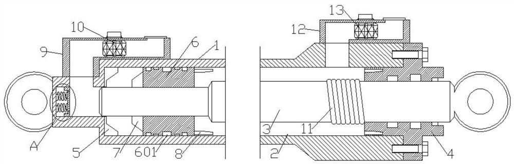
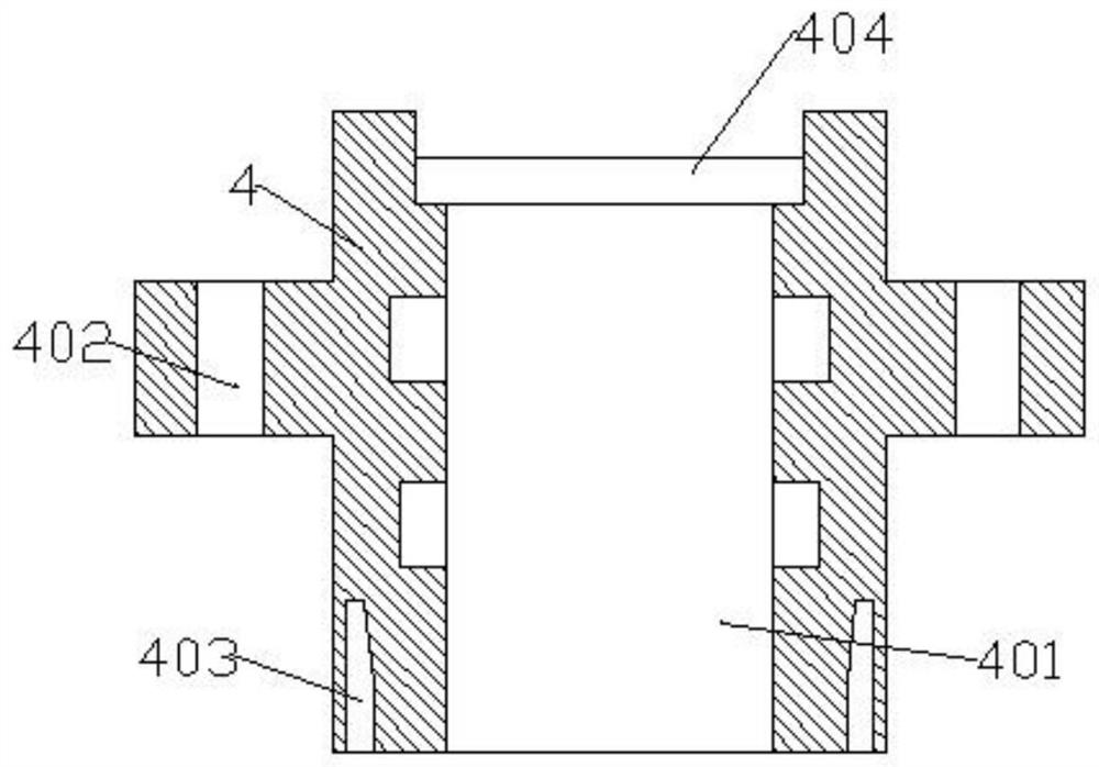
[0021] see Figure 1-4 As shown, the present invention is a hydraulic oil cylinder with high buffer performance, comprising a cylinder barrel 1, an oil cavity 2 is arranged in the cylinder barrel 1, a piston rod 3 is arranged in the oil cavity 2, and an end cover 4 is arranged at one end of the cylinder barrel 1 There is a sliding hole 401 in the center of the end cover 4, the piston rod 3 is slidably installed in the end cover 4, the...


PUM


Abstract

The invention discloses a hydraulic oil cylinder with high buffering performance, comprising a cylinder tube, an oil cavity is arranged in the cylinder tube, a piston rod is arranged in the oil cavity, and an end cover is arranged at one end of the cylinder tube. The invention reduces the running speed of the piston rod by changing the injection speed of the hydraulic oil through the first regulating valve and the second regulating valve, and achieves the buffering effect from the outside of the oil cylinder. The hole is matched with the first buffer spring, and the buffer plug on the other end of the piston cooperates with the buffer cover and the sliding cover in the buffer cavity and the second buffer spring, which buffers the speed of the extension and retraction of the piston rod, and then achieves the buffer effect from the inside of the oil cylinder. The multiple buffer effects realize the buffer braking of the high-speed hydraulic cylinder, which is resistant to high-pressure impact and will not affect the reliability of the seals, greatly improves the service life of the high-speed hydraulic cylinder, and solves the problem of the single buffering method and poor buffering effect in the prior art. technical issues.

Description

technical field [0001] The invention relates to the technical field of hydraulic oil cylinders, in particular to a hydraulic oil cylinder with high buffer performance and a working method thereof. Background technique [0002] In the hydraulic system, the hydraulic cylinder is one of the essential hydraulic components. When the hydraulic cylinder moves at a high speed to the end of the stroke, severe mechanical collisions often occur, which not only affects the working performance of the mechanical equipment, but also damages the hydraulic cylinder and Other components of the hydraulic system are very dangerous and affect the service life of the hydraulic cylinder after a long time. In the prior art, the buffering method of the hydraulic cylinder is single, and the buffering effect is general. SUMMARY OF THE INVENTION [0003] The object of the present invention is to provide a hydraulic oil cylinder with high buffer performance and a working method thereof, and solve the...

Claims


Application Information

Patent Timeline
Patent Type & Authority Patents(China)
IPC IPC(8): F15B15/22F15B15/14F15B15/20F16J15/16F16J9/00
CPCF15B15/22F15B15/226F15B15/227F15B15/149F15B15/1433F15B15/1438F15B15/1447F15B15/1452F15B15/1461F15B15/202
Inventor 姜珠刚
Owner 扬州市正浩液压机械设备有限公司
Why Eureka
Try Eureka