
Low-temperature and constant-temperature liquid circulating device and dewatering method thereof

A technology of circulation device and constant temperature liquid, applied in the field of low temperature and constant temperature, which can solve the problems of long maintenance time, easy mixing of water, and many maintenance operations.

Inactive Publication Date: 2021-04-09
上海谙邦半导体设备有限公司
View PDF0 Cites 6 Cited by
  • Summary
  • Abstract
  • Description
  • Claims
  • Application Information

AI Technical Summary

Problems solved by technology

[0006] In order to solve the problem that the existing low temperature constant temperature liquid circulation device is easy to mix water in the circulating liquid and water removal will lead to long maintenance time, many maintenance operations and loss of equipment production capacity, the purpose of the present invention is to provide a new low temperature constant temperature liquid circulation Device and method for removing water

Method used


Image

  • Low-temperature and constant-temperature liquid circulating device and dewatering method thereof
  • Low-temperature and constant-temperature liquid circulating device and dewatering method thereof
  • Low-temperature and constant-temperature liquid circulating device and dewatering method thereof

Examples


Embodiment 1

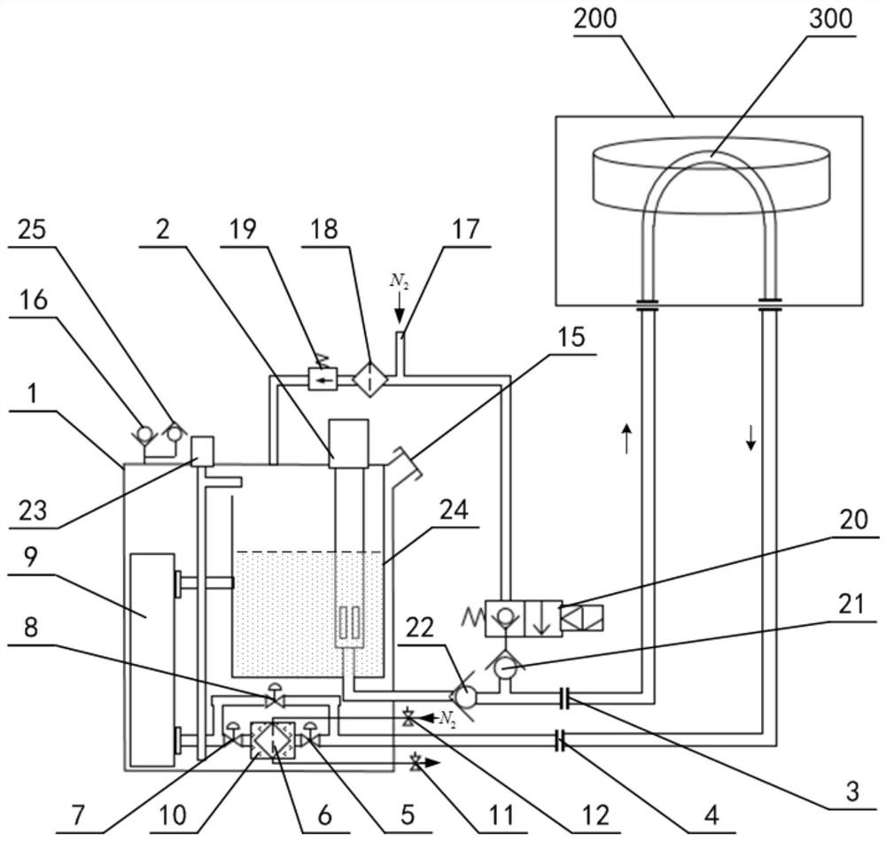
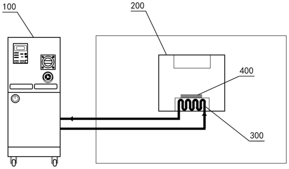
[0059] Such as Figure 2~3 As shown, the low-temperature constant temperature liquid circulation device provided in this embodiment includes a circulating liquid storage tank 1, a circulating pump 2, an output joint 3, a return joint 4, a first normally open stop valve 5, an ice crystal filter 6, Second normally open shut-off valve 7, normally closed shut-off valve 8, heat exchanger 9, heater 10, first valve 11, second valve 12, exhaust joint ( figure 2 not shown in ) and the first nitrogen fitting ( figure 2 not shown in), wherein, the heater 10 is used to heat the ice crystal filter 6; the circulation pump 2 is used to pressurize the circulating fluid in the circulating fluid storage tank 1 into the output joint 3. The output joint 3 is used to connect to one end of the temperature control liquid pipeline 300 in the temperature controlled device 200, and the return joint 4 is used to connect to the other end of the temperature control liquid pipeline 300; the return joint...


PUM


Abstract

The invention relates to the technical field of low temperature and constant temperature, and discloses a low-temperature and constant-temperature liquid circulating device and a dewatering method thereof. According to the low-temperature and constant-temperature liquid circulating device and the dewatering method thereof, on one hand, an ice crystal filter and a plurality of stop valves are additionally arranged in a circulating liquid loop, so that a pair of parallel standby branch and common branch can be formed, when circulating liquid flows through the common branch where the ice crystal filter is located, mixed water can be effectively intercepted and collected due to the fact that the water is frozen into ice cubes, the phenomena that a capillary pipeline in a temperature control liquid pipeline is blocked in the follow-up circulating process, and component cooling faults are caused can be solved, the temperature control stability is guaranteed, on the other hand, a heater, an exhaust connector, a nitrogen connector and a plurality of valves are continuously and additionally arranged for the ice crystal filter, when the standby branch is switched to replace the common branch to keep the circulating liquid loop to be connected, water in the ice crystal filter can be heated and purged in an isolated mode, and therefore on the premise that the circulating liquid loop is not interrupted, the maintenance time can be shortened, the maintenance operation can be reduced, and the equipment productivity loss can be reduced.

Description

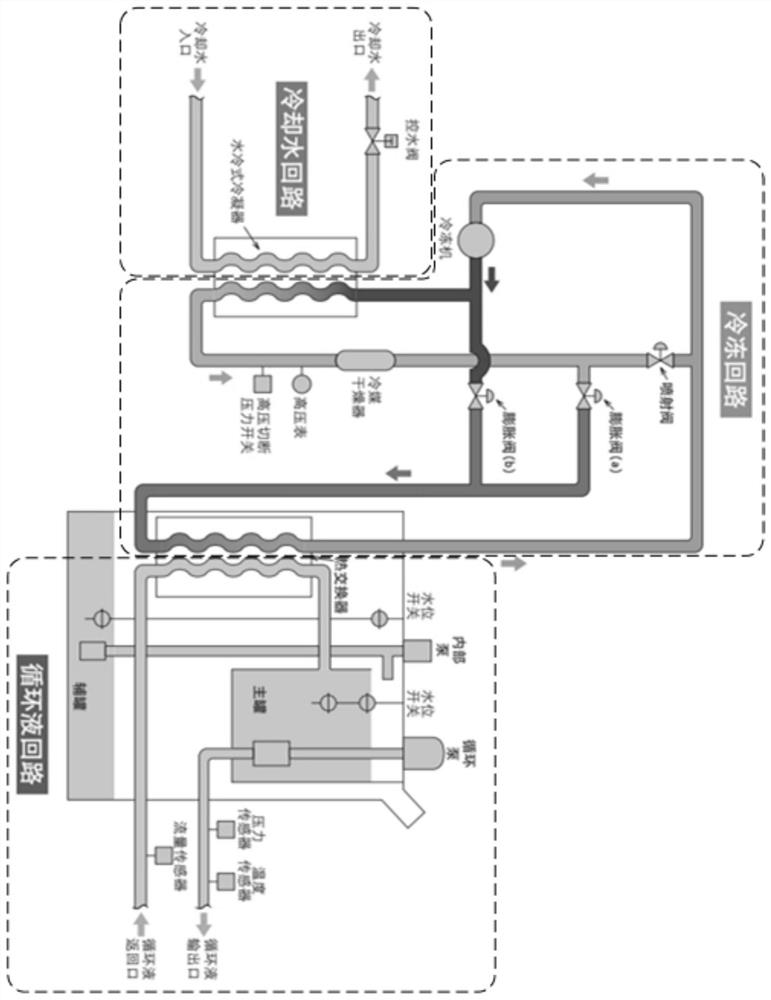
technical field [0001] The invention belongs to the technical field of low temperature constant temperature, and in particular relates to a low temperature constant temperature liquid circulation device and a water removal method thereof. Background technique [0002] In a typical semiconductor manufacturing process, products need to be processed in process equipment to complete key processes. Different process equipment requires different temperature environments (for example, high plasma density etching process usually requires a low temperature environment of -10 to -20 degrees Celsius, and even some very few processes require a harsh environment of -100 degrees Celsius), among which process equipment The low temperature environment is usually provided by the low temperature constant temperature liquid circulation device connected to the temperature control liquid pipeline in the process equipment. Such as figure 1 As shown, the existing low-temperature constant tempera...

Claims


Application Information

Patent Timeline
Patent Type & Authority Applications(China)
IPC IPC(8): F25D17/02F26B21/14
CPCF25D17/02F26B21/14
Inventor 许文泽邱勇
Owner 上海谙邦半导体设备有限公司
Learn More