Charging control circuit, high-voltage control box and charging pile

A charging control and high-voltage control technology, applied in battery circuit devices, battery/fuel cell control devices, charging stations, etc., can solve the problems of cumbersome wiring, etc., and achieve the effect of overcoming cumbersome wiring, convenient wiring, and solving cumbersome wiring

Pending Publication Date: 2021-04-09
深圳市优力特技术有限公司
View PDF0 Cites 0 Cited by
  • Summary
  • Abstract
  • Description
  • Claims
  • Application Information

AI Technical Summary

Problems solved by technology

[0003] The technical problem to be solved by the embodiments of the present invention is to provide a charging control circuit, a high-voltage control box and a charging pile to solve the technical problem of cumbersome wiring of charging piles on the market

Method used


Image

  • Charging control circuit, high-voltage control box and charging pile
  • Charging control circuit, high-voltage control box and charging pile
  • Charging control circuit, high-voltage control box and charging pile

Examples


no. 1 example

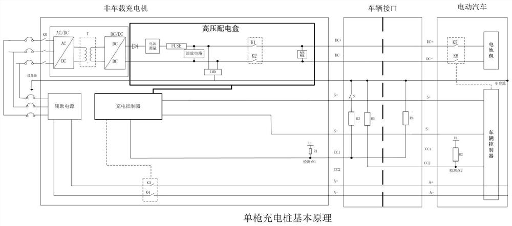
[0025]Such asfigure 2 As shown, the present embodiment is a charging control circuit of a single-played charging pile, and the charging control circuit includes a first charge circuit, a high pressure control circuit.

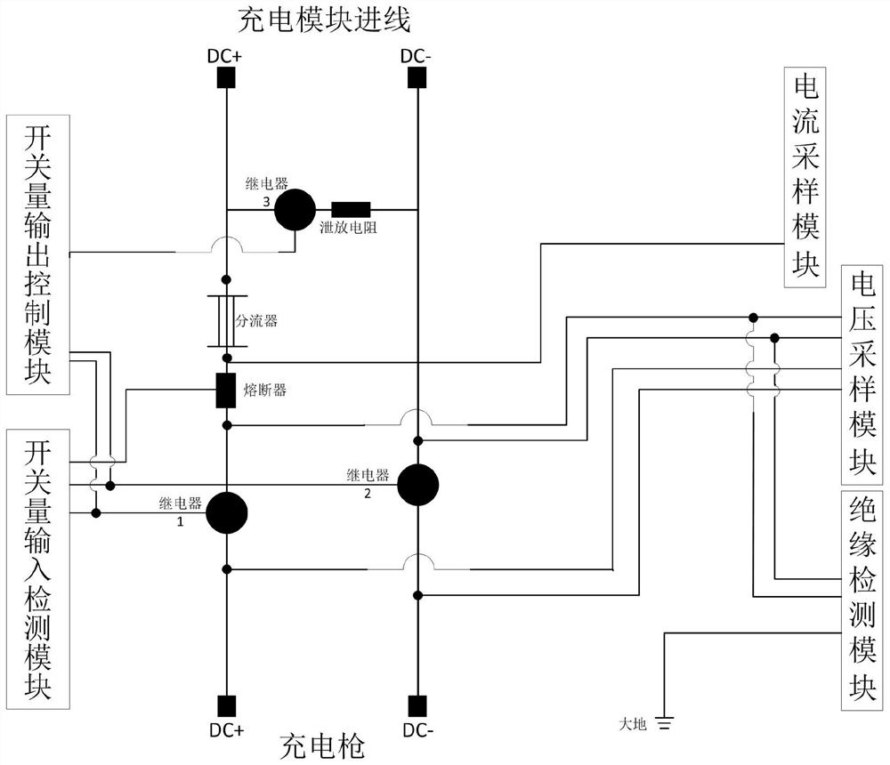
[0026]Preferably, the first charge circuit includes a first relay, a first fuse, a first substrate, a second relay, a first leakage circuit. The first leak circuit includes a third relay, a first leak resistor electrically connected to the third relay, and the connection of the first charge circuit uses the existing general standard connection mode.

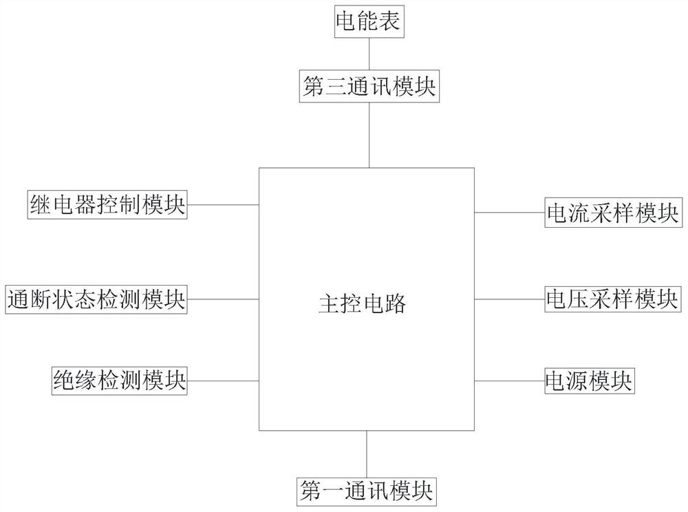
[0027]Preferably, the high voltage control circuit includes: a master circuit, a master circuit integration, a master module chip. The high voltage control circuit also includes a turning-off state detection module, a relay control module, a current sampling module, a voltage sampling module, an insulating detection module, respectively, respectively, respectively.

[0028]Preferably, the first relay, the second relay, and the f...

Embodiment 2

[0039]Such asFigure 4As shown, the present embodiment is a charge control circuit for a double gun charging pile, and the charging control circuit of Example 2 includes a first charge circuit, a high pressure control circuit, wherein the difference between the first charging circuit is to connect the circuit connection. At different nodes, the location does not affect the normal operation of the first charging circuit, the high pressure control circuit is the same as the connection of the electronic components of the first charge circuit.

[0040]The second embodiment of the charging control circuit also includes a second charge circuit, and a high voltage relay for power allocation, a high voltage relay respectively disconnects a high voltage control circuit, and a relay control module is electrically connected.

[0041]Preferably, the second charge circuit includes a fourth relay, a second fuse, a second substister, a fifth relay, a second leakage circuit. The second leakage circuit inc...


PUM


Abstract

The invention relates to a charging control circuit, a high-voltage control box and a charging pile. The charging control circuit comprises a first charging circuit, the first charging circuit comprises a first relay, a first fuse, a first shunt, a second relay and a first bleeder circuit, and the charging control circuit also comprises a high-voltage control circuit; the high-voltage control circuit comprises a main control circuit; and the high-voltage control circuit comprises an on-off state detection module, a relay control module, a current sampling module, a voltage sampling module, an insulation detection module and a first communication module which are electrically connected with the main control circuit. By adopting the technical means that the charging control circuit collects the data of the charging circuit and the states of the corresponding electronic elements, the technical problems that charging piles on the market are tedious in wiring and messy in circuit are solved, and the technical effects of industrial integration and convenient wiring are achieved.

Description

Technical field[0001]The present invention relates to the field of charging piles, and more particularly to a charging control circuit, a high pressure control cartridge, and a charging pile.Background technique[0002]With the continuous promotion of new energy, there are many charging pile products on the market. At present, the general charging piles are basically adopted by electric vehicle chargers that meet the national standard "GB / T 18487.1", "GB / T 27930" will Relay control signal line, state feedback signal line, voltage current sampling line, etc., as needed to connect to the charging controller, with continuous practice, discovery that the program has a cumbersome, complex production process, and later inconvenient in equipment troubleshooting The problem of maintenance, at the same time, the charging pile is installed, and the professional technician is required to install, causing the waste of manpower and material resources.Inventive content[0003]The technical proble...

Claims


Application Information

Patent Timeline
Patent Type & Authority Applications(China)
IPC IPC(8): H02J7/00B60L53/16B60L53/31B60L58/10
CPCH02J7/0013H02J7/00034H02J7/00712B60L53/16B60L53/31B60L58/10Y02T10/70Y02T10/7072Y02T90/12Y02T90/14Y02T90/16
Inventor 郑英龙杨晓峰陈波翁俊伟
Owner 深圳市优力特技术有限公司
Why Eureka
Try Eureka