
A magnetic levitation planar motor with good heat dissipation and its working method

A planar motor and heat dissipation technology, which is applied in the direction of electromechanical devices, electrical components, electric components, etc., to achieve the effect of convenient movement and good heat dissipation

Active Publication Date: 2021-12-31
常州迅捷磁浮技术有限公司
View PDF7 Cites 0 Cited by
  • Summary
  • Abstract
  • Description
  • Claims
  • Application Information

AI Technical Summary

Problems solved by technology

[0004] The purpose of the present invention is to provide a magnetic levitation planar motor with good heat dissipation and its working method, so as to solve the following technical problems: (1) before the maglev planar motor works, two lifting cylinders are opened, and the piston rod of the lifting cylinder drives the upper connecting plate to descend. The upper connecting plate drives the two lifting rods down, the two lifting rods drive the lower connecting plate down, the lower connecting plate drives the universal wheel down, the universal wheel moves out of the groove in the lifting plate, and the maglev can be moved through the universal wheel Planar motor, after moving the magnetic levitation plane motor to the designated position, turn on the fixed motor, the output shaft of the fixed motor drives the second screw to rotate, the second screw drives the two adjustment sleeves to move towards each other, and the two adjustment sleeves drive four rotary rods Rotate, the four rotating rods drive the lifting plate down, and the lifting plate moves out from the bottom of the lower body to adjust the height of the magnetic levitation plane motor. Through the above structure settings, the magnetic levitation plane motor can meet the adjustment of different heights, and then meet different heights At the same time, the universal wheel can be adjusted in and out from the lifting plate to facilitate the movement of the magnetic levitation plane motor; (2) When the magnetic levitation plane motor is working, open the two installation motors, and the output shaft of the installation motor drives the first screw Rotate, the first lead screw drives the two adjustment blocks to move towards each other, the two adjustment blocks drive the two baffles to move towards each other, the baffles and the heat dissipation fins are staggered, the heat dissipation fins dissipate heat to the inner cavity of the upper base, the permanent magnet array and the electrified coil The array is matched, and the stage is suspended above the energized coil array. When the energized coil array is energized, the stage moves in a six-degree-of-freedom direction above the energized coil array. On the inner wall of the cover, the buffer plate squeezes two buffer springs, and the two buffer springs buffer the impact force on the buffer plate. Through the above structure, the baffle can block the cooling fins when the magnetic levitation planar motor is not in use, preventing External dust enters the upper body, thereby avoiding the situation where the energized coil array absorbs dust. When the maglev planar motor is in use, the heat dissipation fins can help dissipate the heat in the upper body cavity caused by the energized coil array, making the maglev plane The heat dissipation effect of the motor is good; (3) The condensate pump draws the cooling water in the cooling water tank through the connecting pipe, and transports it to the second confluence chamber through the delivery pipe, and the cooling water in the second confluence chamber enters the serpentine pipe, and the serpentine pipe The cooling water enters the first confluence chamber, and flows back into the cooling water tank through the return pipe to form a cooling water cycle. The temperature of the serpentine tube is lowered, and the driving motor is turned on. The output shaft of the driving motor drives the second pulley to rotate, and the second pulley cooperates with the belt to drive several When the pulley rotates, the pulley drives the corresponding serpentine tube to rotate. When the serpentine tube rotates, a cold wind is formed in the inner cavity of the upper base, and the cold air cools down the energized coil array on the upper base. The internal rotation and the cooling water flowing in the internal circulation can cool down the inner cavity of the upper body, the cooling effect is good, and the temperature of the energized coil array is prevented from being too high

Method used


Image

  • A magnetic levitation planar motor with good heat dissipation and its working method
  • A magnetic levitation planar motor with good heat dissipation and its working method
  • A magnetic levitation planar motor with good heat dissipation and its working method

Examples


Embodiment Construction

[0032] The following will clearly and completely describe the technical solutions in the embodiments of the present invention with reference to the accompanying drawings in the embodiments of the present invention. Obviously, the described embodiments are only some, not all, embodiments of the present invention. Based on the embodiments of the present invention, all other embodiments obtained by persons of ordinary skill in the art without creative efforts fall within the protection scope of the present invention.

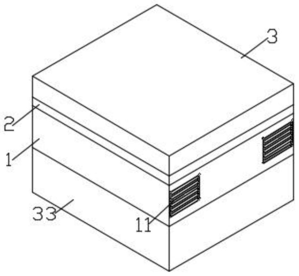
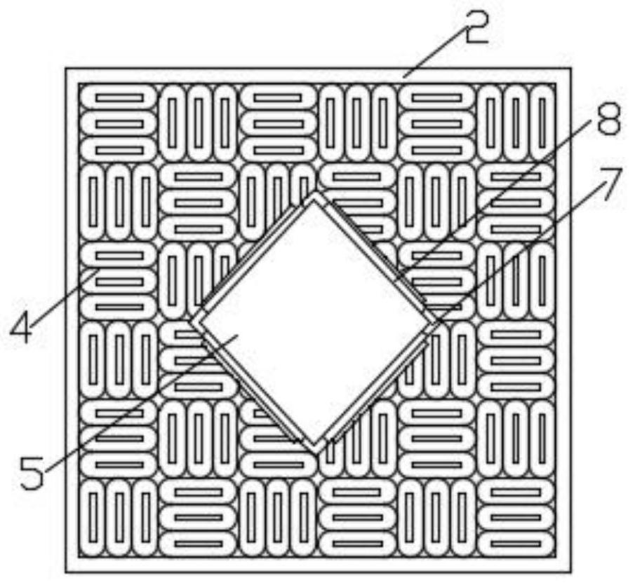
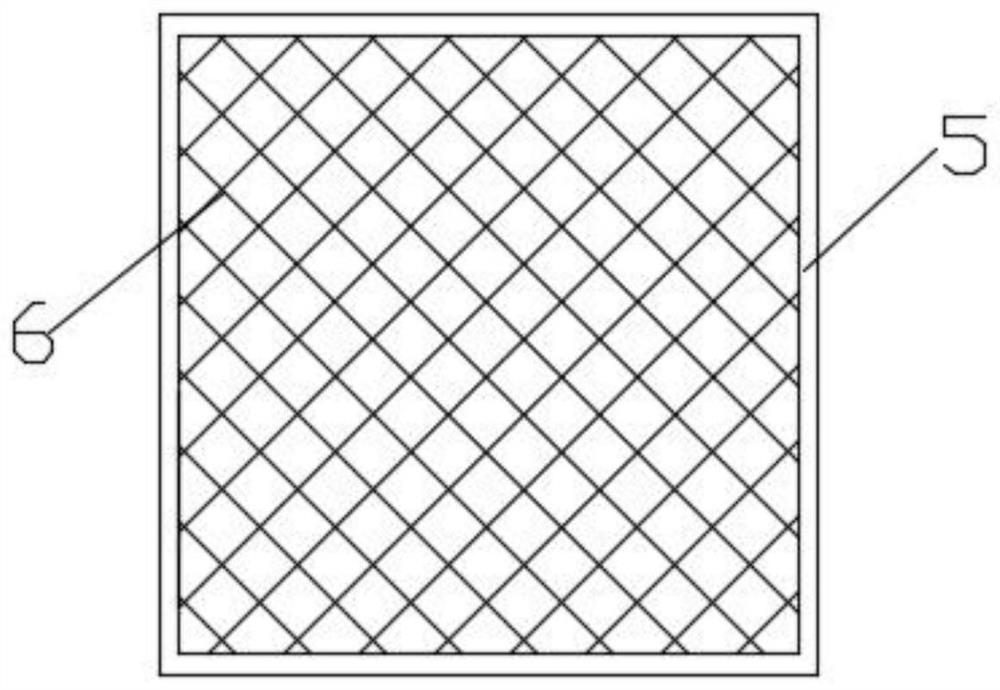
[0033] see Figure 1-9 As shown, the present invention is a magnetic levitation planar motor with good heat dissipation, comprising a energized coil array 4 and a permanent magnet array 6, the energized coil array 4 is installed on the substrate 2, the permanent magnet array 6 is arranged in the stage 5, and the substrate 2 Installed on the upper base body 1, an installation cover 3 is installed above the substrate 2, four installation shells 8 are installed on the...


PUM


Abstract

The invention discloses a maglev planar motor with good heat dissipation and a working method thereof, which comprises a energized coil array and a permanent magnet array, the energized coil array is installed on a substrate, the permanent magnet array is arranged in an object stage, and the substrate is installed on an upper base , there is an installation cover above the substrate, four installation shells are installed on the stage, a buffer plate is arranged on the installation shell, four heat dissipation fins are installed on the upper base body, the heat dissipation fins can accelerate the heat dissipation of the inner cavity of the upper base, and the upper base There are four baffles in the body, and the four cooling fins correspond to the four baffles one by one. The setting of the baffles can ensure that the external dust will not enter the upper body through the cooling fins when the maglev planar motor is not in use. There are a first confluence chamber and a second confluence chamber. The invention can satisfy the adjustment of different heights, and further satisfy the use of the loading platforms of different heights, and at the same time, the universal wheel can be adjusted in and out from the lifting plate, so as to facilitate the movement of the maglev planar motor.

Description

technical field [0001] The invention relates to the technical field of design of a maglev planar motor, in particular to a maglev planar motor with good heat dissipation and a working method thereof. Background technique [0002] With the advancement of lithography technology and the rapid development of the semiconductor industry, there are four basic performance indicators for lithography equipment: line width uniformity (CD, Critical Dimension Uniformity), focal depth (Focus), overlay (Overlay) and production Rate (Throughput). In order to improve the uniformity of line width, the workpiece table or mask table must improve the horizontal precision positioning capability; in order to improve the focal depth error accuracy, the workpiece table or mask table must improve the vertical precision positioning capability; in order to improve the engraving error of the lithography machine For accuracy, the workpiece stage or mask stage must increase its internal modality to impro...

Claims


Application Information

Patent Timeline
Patent Type & Authority Patents(China)
IPC IPC(8): H02K5/26H02K5/24H02K5/18H02K5/20H02K9/19H02N15/00
CPCH02K5/26H02K5/24H02K5/18H02K5/20H02K9/19H02N15/00
Inventor 于建英夏立影
Owner 常州迅捷磁浮技术有限公司
Learn More