Supercharge Your Innovation With Domain-Expert AI Agents!

Dynamic power supply shifting

A power supply voltage, low power supply voltage technology, applied in the field of receivers, can solve problems such as failures and device pressure

Active Publication Date: 2021-04-09
QUALCOMM INC
View PDF17 Cites 0 Cited by
  • Summary
  • Abstract
  • Description
  • Claims
  • Application Information

AI Technical Summary

Problems solved by technology

Considering the difference between the various supply voltages, if the voltage difference across the terminals (gate-to-source, gate-to-drain, or drain-to-source) of a device input into the receiver exceeds the maximum rated voltage of the device level, the device may become stressed and malfunction

Method used


Image

  • Dynamic power supply shifting
  • Dynamic power supply shifting
  • Dynamic power supply shifting

Examples


Embodiment Construction

[0027] Aspects disclosed in the following description and associated drawings are directed to particular embodiments. Alternative embodiments may be devised without departing from the scope of the invention. Additionally, well-known elements may not be described in detail or may be omitted so as not to obscure the relevant details. The disclosed embodiments may be suitably included in any electronic device.

[0028]Referring now to the drawings, several exemplary aspects of the disclosure are described. The word "exemplary" is used herein to mean "serving as an example, instance, or illustration." Any aspect described herein as "exemplary" is not necessarily to be construed as preferred or advantageous over other aspects. Furthermore, the terminology used herein is for the purpose of describing particular embodiments and is not intended to be limiting.

[0029] As noted, integrated circuits (ICs) continue to evolve to smaller and smaller process nodes, and at these smaller...


PUM


Abstract

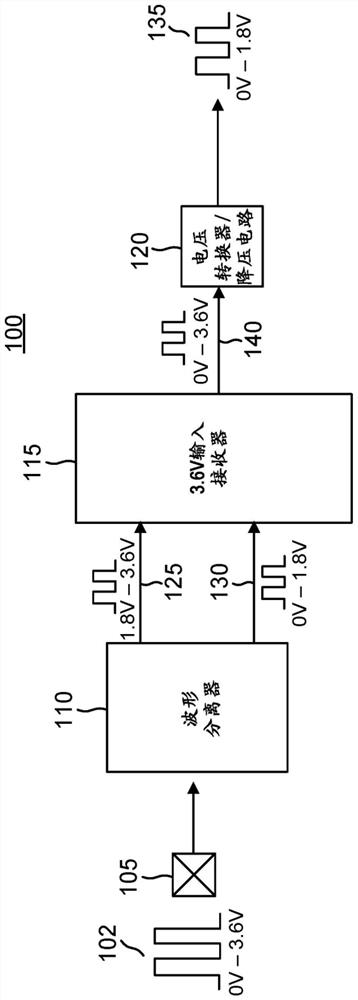
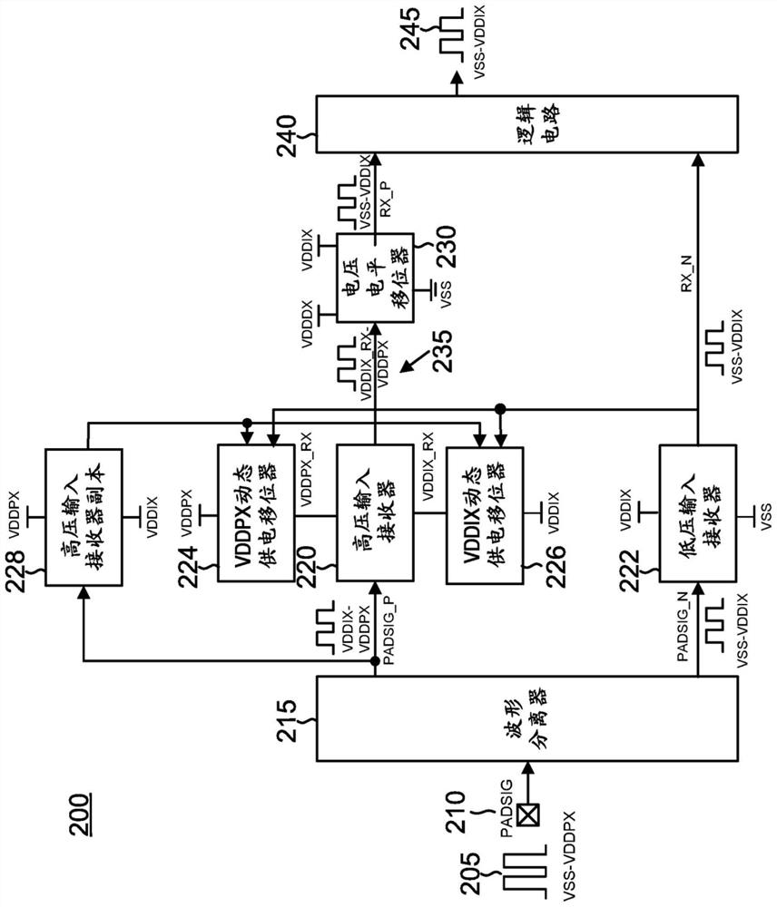
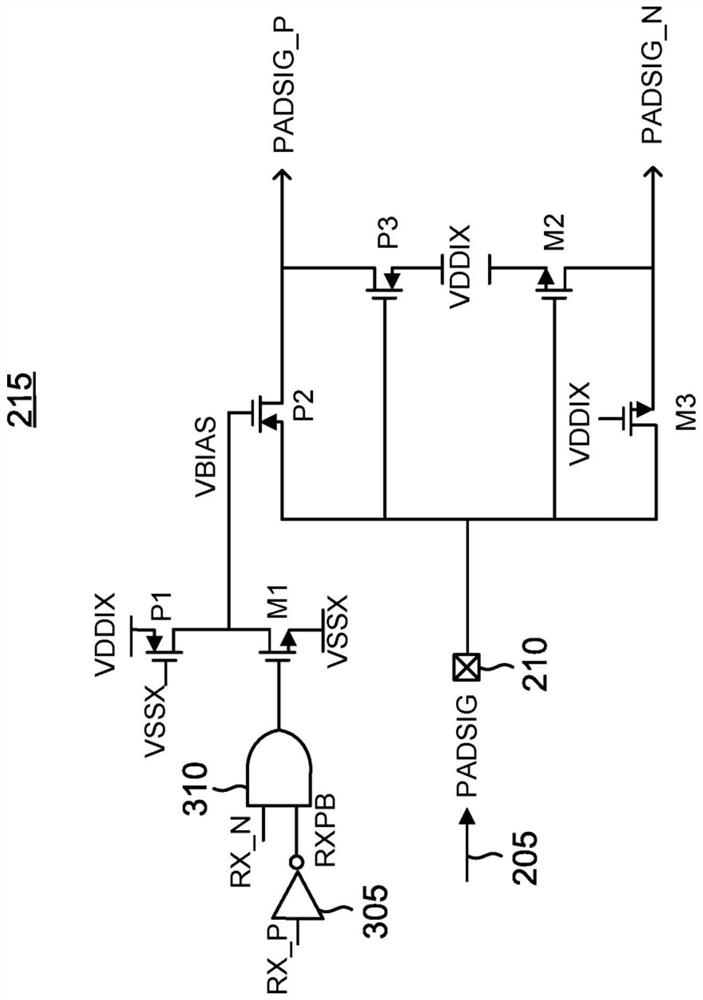
Aspects generally relate to receivers, and in particular to a receiver that converts a high-voltage input signal (102) into a low-voltage signal (135). A high voltage input signal (102) is split into a upper portion (125) and a lower portion (130). The upper portion is coupled to a high input receiver (115) that is powered by dynamic supply shifters that can vary supply voltage during operation to optimize switching.

Description

[0001] Cross References to Related Applications [0002] This patent application claims the benefit of patent application 16 / 114,524, entitled "Dynamic Power Transfer," filed August 28, 2018, and assigned to the present assignee and expressly incorporated herein by reference. technical field [0003] Aspects of the present disclosure relate generally to receivers, and in particular to receivers that convert high voltage input signals to low voltage signals. Background technique [0004] As semiconductor technology has evolved to smaller process nodes, supply voltages have shrunk as transistors have scaled. Likewise, the input / output (I / O) supply voltage for I / O signals has also been scaled down. However, there may still be a need to support input / output (I / O) standards from the signal side with higher voltage levels. Accordingly, an integrated circuit (IC) may require an input receiver that can receive an input signal at a first voltage level and output a signal at a seco...

Claims


Application Information

Patent Timeline
Patent Type & Authority Applications(China)
IPC IPC(8): H03K19/003H03K19/0185
CPCH03K19/00369H03K19/018507G06F1/26H03K3/3565H03K5/08H03K5/24H03K17/102H03K19/00315
Inventor W·J·陈C-G·谭S·劳
Owner QUALCOMM INC
Features
  • R&D
  • Intellectual Property
  • Life Sciences
  • Materials
  • Tech Scout
  • Unparalleled Data Quality
  • Higher Quality Content
  • 60% Fewer Hallucinations
Learn More