
Stable strong-tension-resistant zipper

A zipper and stable technology, applied in the field of zippers, can solve problems such as easy cracking, zippers that cannot be closed, zippers that are not strong against pressure, etc., and achieve the effect of low production cost, strong stable structure, and wide application

Pending Publication Date: 2021-04-13
陆境燃
View PDF6 Cites 0 Cited by
  • Summary
  • Abstract
  • Description
  • Claims
  • Application Information

AI Technical Summary

Problems solved by technology

[0002] At present, the zipper structure on the market is that the same chain teeth on the left and right sides are squeezed into the space left by the pressing head to form a whole. Many zippers will not close after a period of time. If a certain tooth position is crooked, misaligned or worn out, even if it is a new zipper, some chain teeth are made of metal such as copper, aluminum or even iron. I have never used it, but because it has been placed for one or two years, and the normal wardrobe placed at home will cause problems with the surface contact of the sprockets and they will not close together well, so many metal zippers will be broken after a long time. After all, ordinary There is still a problem between the surface and running-in when you pack the temperature and humidity conditions at home, and many zippers are easy to crack when used because they are not strong in pressure resistance, so many zippers cannot be used on fabrics or tying tools that need to be combined. , can only be tied with buttons and ropes, etc., so it is not as good as zippers in terms of convenience and closure, so it is subject to many restrictions in use scenarios

Method used


Image

  • Stable strong-tension-resistant zipper
  • Stable strong-tension-resistant zipper
  • Stable strong-tension-resistant zipper

Examples


Embodiment Construction

[0013] Attached below Figure 1-7 To further illustrate the present invention, what is described is only a part of the embodiments of the present invention, and various changes, equivalent changes and modifications made by the skilled person to the present invention also fall within the scope of the claims of the present invention.

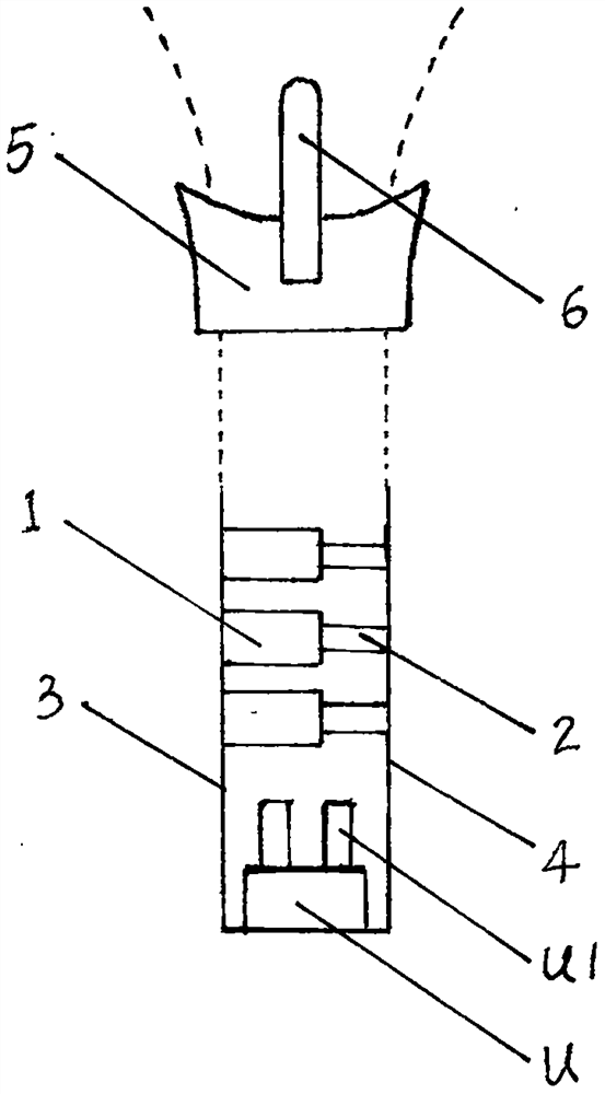
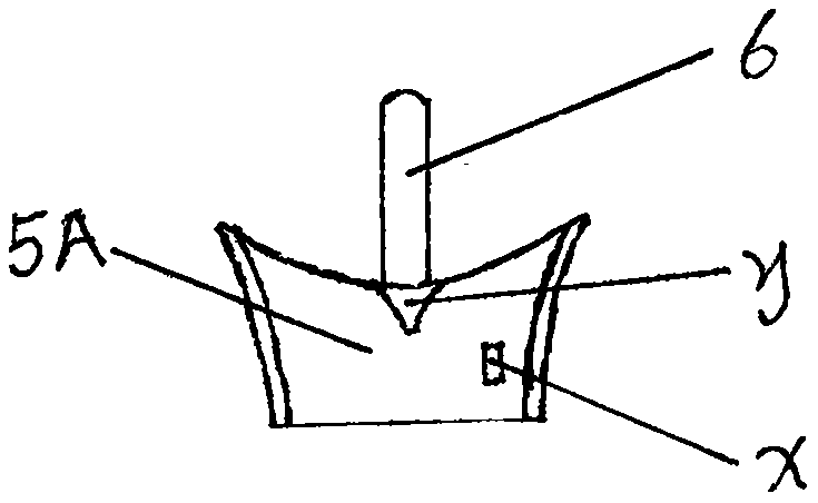
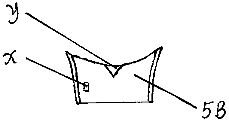
[0014] see figure 1 The socket U and inserting rod U1 are used in the same way as ordinary zippers. The pressing head 5 that is pulled up and down has a pull piece 6. The internal structure of the pressing head 5 is as follows: figure 2 It is the upper cover plate 5A of the pressing head, image 3 It is the lower cover plate 5B of the pressing head, figure 2 image 3 There are corresponding internal convex points X of the pressing head and connecting points Y of the upper and lower cover plates of the pressing head 5. The fabric piece is connected to the stable card box 1 on the left side of the zipper and the stable card plug 2 on the right ...


PUM


Abstract

The invention discloses a stable strong-tension-resistant zipper. The zipper comprises a socket, an inserting rod, a pressing head, a fabric piece and the like, the fabric piece is connected with a stable clamping box body on the left side and a stable clamping plug on the right side of the zipper through fabric threads, the stable clamping box body is provided with a warped strip groove, a warped strip is placed in the warped strip groove, an upper warped strip and a lower warped strip are fixed and positioned by two warped strip movable central columns in the stable clamping box body, and the inner ends of the two warped strips are bounced off by a spring, so that a warped strip pressing point at the left end of one warped strip is kept outwards bounced, and a warped strip clamping point is inwards stressed and bounced; and when a convex point in the pressing head presses the warped strip pressing point, the warped strip clamping point at the right end of one warped strip is elastically pressed outwards, and when a pulling head is pulled up and down, and a connecting point of an upper cover plate and a lower cover plate can separate chains on the left side and the right side or press the chains upwards. The zipper is simple in structure, low in production cost, widely applicable and stronger in stable structure, especially can be applied to zippers bearing stronger pulling force without cracking and separating, and is durable.

Description

technical field [0001] The invention belongs to the technical field of zippers, in particular to a zipper which is stable and resistant to strong pulling force. Background technique [0002] At present, the zipper structure on the market is that the same chain teeth on the left and right sides are squeezed into the space left by the pressing head to form a whole. Many zippers will not close after a period of time. If a certain tooth position is crooked, misaligned or worn out, even if it is a new zipper, some chain teeth are made of metal such as copper, aluminum or even iron. I have never used it, but because it has been placed for one or two years, and the normal wardrobe placed at home will cause problems with the surface contact of the sprockets and they will not close together well, so many metal zippers will be broken after a long time. After all, ordinary There is still a problem between the surface and running-in when you pack the temperature and humidity conditions...

Claims


Application Information

Patent Timeline
IPC IPC(8): A44B19/26A44B19/24
CPCA44B19/26A44B19/24
Inventor 陆境燃
Owner 陆境燃
Learn More