Disc cutting device

A technology for cutting devices and discs, applied in the direction of shearing devices, attachments of shearing machines, maintenance and safety accessories, etc.

Inactive Publication Date: 2021-04-13
郭献进
View PDF0 Cites 0 Cited by
  • Summary
  • Abstract
  • Description
  • Claims
  • Application Information

AI Technical Summary

Problems solved by technology

[0003] Aiming at the deficiencies in the prior art, the purpose of the present invention is to provide a disc cutting device to solve the existing problems

Method used


Image

  • Disc cutting device
  • Disc cutting device
  • Disc cutting device

Examples


Embodiment Construction

[0019] In order to make the technical means, creative features, goals and effects achieved by the present invention easy to understand, the present invention will be further described below in conjunction with specific embodiments.

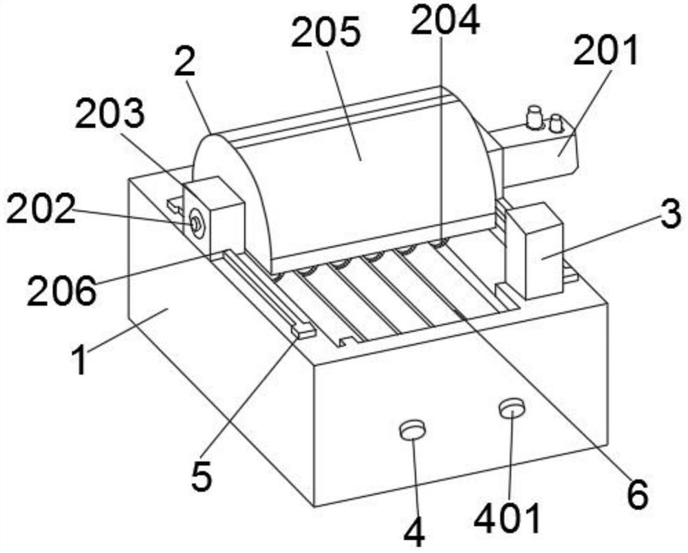
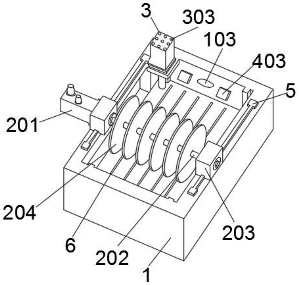
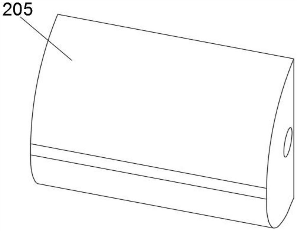
[0020] see Figure 1-Figure 7 , the present invention provides a technical solution for a disc cutting device: its structure includes a base 1, a cutting device 2, a purification device 3, a fixing device 4, a sliding track 5, and a cutting track 6, and the base 1 is provided with a cutting cavity 101 and The cutting chamber 101 is integrally formed with the base 1, the cutting device 2 is slidably connected to the sliding track 5, the purification device 3 is located on the side above the base 1, and the fixing device 4 is located on the side of the base 1. One side of the cutting cavity 101, the sliding track 5 is provided with two and the two sliding tracks 5 are located on both sides of the base 1, the cutting track 6 is located on the cutting...


PUM


Abstract

The invention discloses a disc cutting device which structurally comprises a base, a cutting device body, a purifying device, a fixing device, sliding rails and a cutting rail. A cutting cavity is formed in the base, the cutting cavity and the base are integrally formed, the cutting device body is connected to the sliding rails in a sliding mode, the purifying device is located on one side of the upper portion of the base, the fixing device is located on one side of the cutting cavity, the two sliding rails are located on the two sides of the base, the cutting rail is located on the cutting cavity, and the cutting rail and the cutting cavity are integrally formed. Chippings generated in the working process can be blocked by a protective cover, so that the chippings are prevented from flying around, the protective cover is made of a transparent material, the situation in the protective cover can be seen in the working process, the chippings blocked by the protective cover can be sucked away by a dust suction pump, waste gas exhausted in the working process of the dust suction pump can be purified by an air purifier and then exhausted, and therefore environmental pollution cannot be caused.

Description

technical field [0001] The invention relates to a disc cutting device, which belongs to the technical field of cutting machines. Background technique [0002] Cutting machines are used in metal and non-metal industries. Generally speaking, non-metal industries are more detailed, such as stone cutting machines for cutting stones, water cutting machines, sawtooth cutting machines, cutting cloth and plastics, and laser cutting for chemical fiber products. Machine, blade cutting machine, cutting metal materials are flame cutting machine, plasma cutting machine, flame cutting machine which is divided into CNC cutting machine, and manual two categories, manual categories are small sports car, semi-automatic, pure manual , CNC has, gantry type CNC cutting machine, cantilever type CNC cutting machine, desktop CNC cutting machine, intersecting line CNC cutting machine, etc., the existing disc cutting machine debris will fly randomly during cutting, which not only affects The air als...

Claims


Application Information

Patent Timeline
Patent Type & Authority Applications(China)
IPC IPC(8): B23D19/00B23D33/00B23Q11/00B23Q11/08
CPCB23D19/00B23D33/00B23Q11/0046B23Q11/08B23Q2011/0808
Inventor 郭献进
Owner 郭献进
Why Eureka
Try Eureka