
Continuous automatic welding device for steel plates

An automatic welding and steel plate technology, applied in the direction of auxiliary equipment, welding equipment, auxiliary welding equipment, etc., can solve problems such as waste, and achieve the effect of saving resources and good automation effect

Inactive Publication Date: 2021-04-13
汪祖平
View PDF0 Cites 0 Cited by
  • Summary
  • Abstract
  • Description
  • Claims
  • Application Information

AI Technical Summary

Problems solved by technology

[0002] Steel plates are often cut continuously during the production and processing process, leaving a small part of waste steel plates in the end. Generally, manufacturers will pile up these steel plates and sell them directly as scrap iron. This method is obviously too wasteful.

Method used


Image

  • Continuous automatic welding device for steel plates
  • Continuous automatic welding device for steel plates
  • Continuous automatic welding device for steel plates

Examples


Embodiment Construction

[0019] The implementation of the present invention will be illustrated by specific specific examples below, and those skilled in the art can easily understand other advantages and effects of the present invention from the content disclosed in this specification. The "above" and "below" mentioned in this embodiment are consistent with the directions above and below the drawings themselves, which are only for the convenience of description and clarification, and are not used to limit the scope of the present invention, and the changes or adjustments of their relative relationships , without substantively changing the technical content, it should also be regarded as the scope of the present invention that can be implemented.

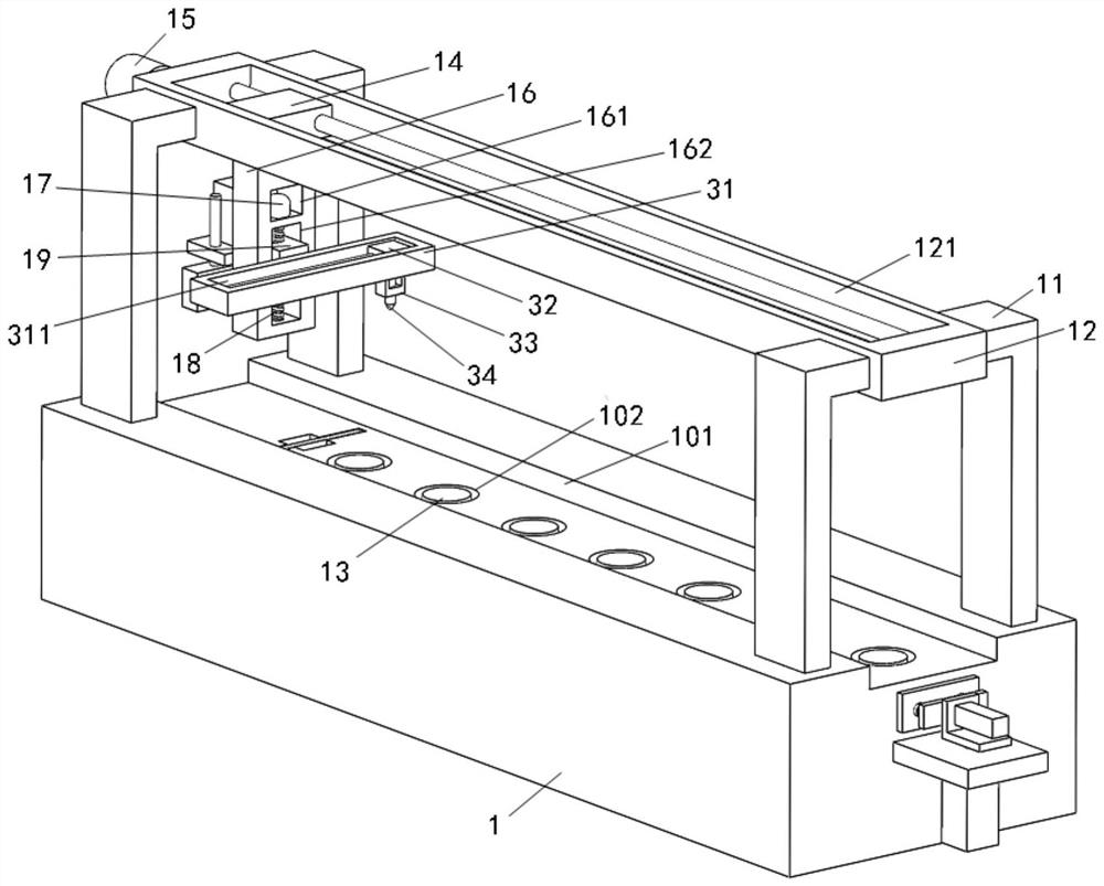
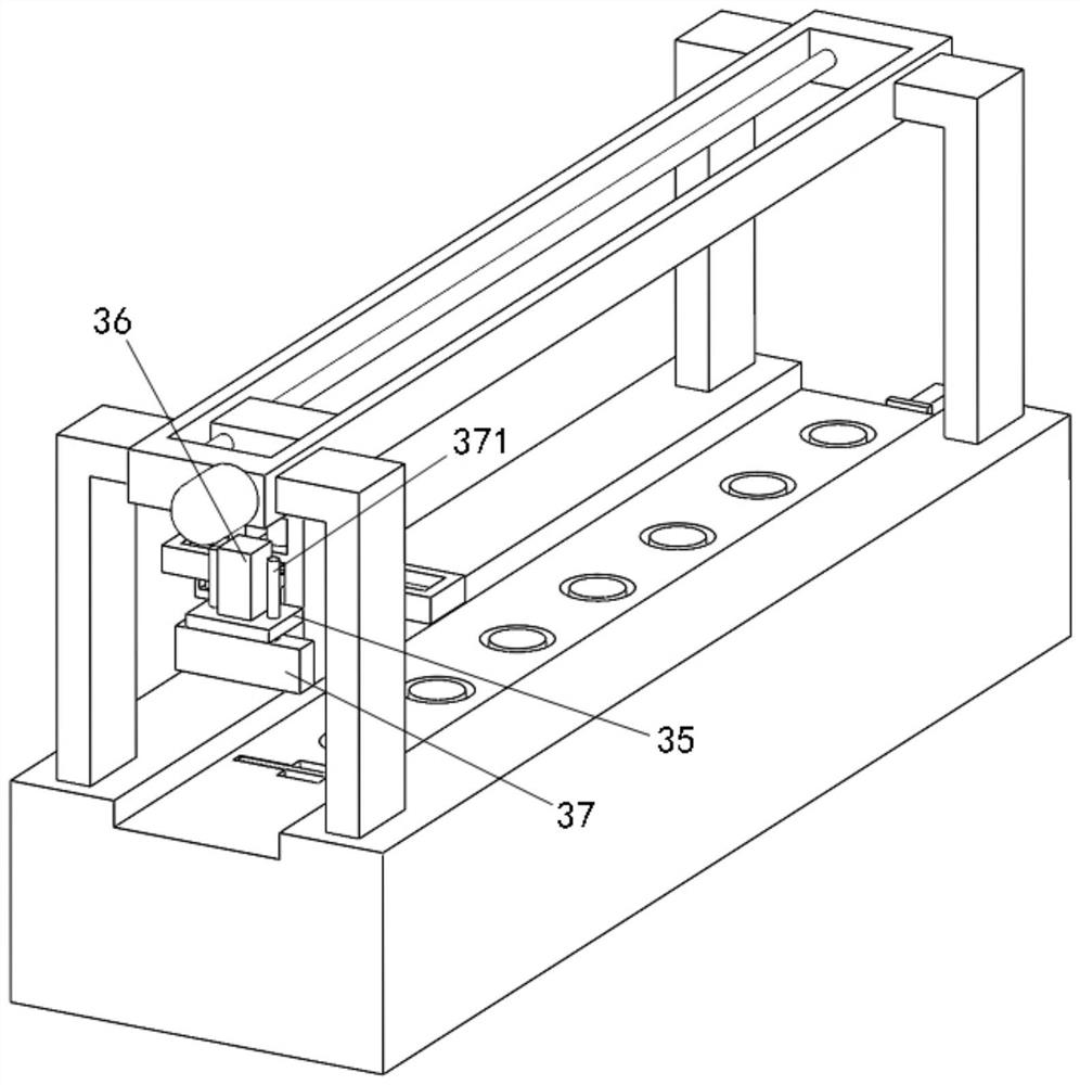
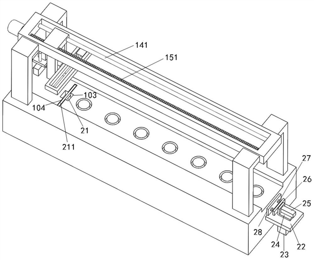
[0020] Depend on Figure 1 to Figure 3 As shown, a continuous automatic welding device for steel plates, including a processing base 1, is characterized in that: the center of the top surface of the processing base 1 is provided with a placement groove 101 ...


PUM


Abstract

The invention discloses a continuous automatic welding device for steel plates. The continuous automatic welding device comprises a machining base, wherein a containing groove is formed in the center of the top face of the machining base, and a movable plate is arranged over the containing groove; a fixed base is arranged on the bottom face of the movable plate, and a lifting block capable of ascending and descending is arranged in the fixed base; a longitudinal welding plate base is fixed to the front side wall of the lifting block; and a longitudinally-moving welding head is arranged at the top of the longitudinal welding plate base. The continuous automatic welding device has the advantages that a plurality of steel plates with the same size can be arranged on the machining base in order and are limited and fixed through two movable limiting pressing plates; a welding gun head capable of ascending, descending and moving is arranged above the steel plates, and the welding gun head can automatically move to the joint of two adjacent steel plates for welding, so that automatic splicing of the steel plates is achieved; and the automation effect is good, and resources are saved.

Description

Technical field: [0001] The invention relates to the technical field of automatic processing equipment, in particular to a continuous automatic welding device for steel plates. Background technique: [0002] Steel plates are often cut continuously during production and processing, leaving a small part of scrap steel plates in the end. Generally, manufacturers will pile up these steel plates and sell them directly as scrap iron. This approach is obviously too wasteful. Contents of the invention [0003] The purpose of the present invention is to address the deficiencies of the prior art, and to provide a continuous automatic welding device for steel plates, which can neatly arrange a plurality of steel plates of the same size on the processing base and control them by two movable limit pressure plates. The steel plate is limited and fixed, and there is a lifting and movable welding gun head above the steel plate. The welding gun head can automatically move to the junction o...

Claims


Application Information

Patent Timeline
Patent Type & Authority Applications(China)
IPC IPC(8): B23K37/04B23K37/02
CPCB23K37/02B23K37/04B23K37/0443
Inventor 汪祖平
Owner 汪祖平
Learn More