Cylinder driving type digital controlled lathe tailstock automatic feeding control method capable of achieving floating tapping

A CNC lathe tailstock, CNC lathe technology, applied in the direction of tailstock/top, turning equipment, manufacturing tools, etc., can solve the problems of low axial dimension control accuracy, inability to automatically feed the tailstock, low processing efficiency, etc. The effect of low cost, increased flexibility, and increased automation

Active Publication Date: 2016-10-12
上海华兑金属有限公司
View PDF6 Cites 0 Cited by
  • Summary
  • Abstract
  • Description
  • Claims
  • Application Information

AI Technical Summary

Problems solved by technology

[0002] CNC lathes are one of the most commonly used automatic processing equipment in mechanical cutting. However, the tailstock of general CNC machine tools cannot be automatically fed, and can only be operated manually, which is time-consuming and laborious, and the processing efficiency is low. Dimensional control accuracy is low

Method used


Image

  • Cylinder driving type digital controlled lathe tailstock automatic feeding control method capable of achieving floating tapping
  • Cylinder driving type digital controlled lathe tailstock automatic feeding control method capable of achieving floating tapping
  • Cylinder driving type digital controlled lathe tailstock automatic feeding control method capable of achieving floating tapping

Examples


Embodiment Construction

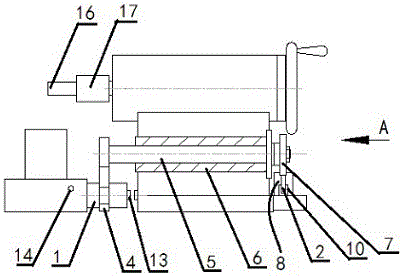
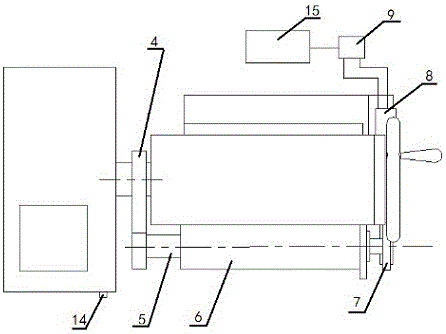
[0017] An automatic feeding control method of a CNC lathe tailstock capable of floating tapping driven by a cylinder, which uses a connecting device that uses a cylinder to realize the engagement and disengagement of the saddle and tailstock of a CNC lathe, including a connecting column 1, Rotating arm assembly, driving assembly and tap assembly, the middle part of the connecting column 1 is provided with a ring groove 3, the connecting column 1 is fixedly connected with the saddle of the CNC lathe, and a pair of sensors 13 are arranged on the shaft end of the connecting column 1 and the side of the tailstock, so that The sensor can be a magnetic effect sensor or a Hall effect sensor, or a photoelectric sensor.

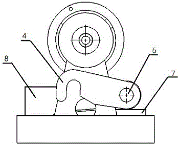
[0018] Described rotating arm assembly comprises rotating arm 4, rotating shaft 5, axle sleeve 6 and bull gear 7, and described axle sleeve 6 is fixed on the front side of CNC lathe tailstock, and described rotating shaft 5 passes through axle sleeve 6, and rotates Th...


PUM


Abstract

The invention provides a cylinder driving type digital controlled lathe tailstock automatic feeding control method capable of achieving floating tapping. A digital controlled lathe saddle and tailstock engaging and disengaging connecting device is adopted and comprises a connecting pillar, a rotating arm component, a driving component and a screw tap component, wherein a ring slot is formed in the middle of the connecting pillar, and a pair of sensors are arranged at the shaft end of the connecting pillar and on the side face of a tailstock; the rotating arm component comprises a rotating arm, a rotating shaft, a shaft sleeve and a big gear, and the shaft sleeve is fixed to the front side face of the digital controlled lathe tailstock; the rotating shaft penetrates through the shaft sleeve, the front end of the rotating shaft is fixedly connected with the rotating arm, the other end of the rotating shaft is fixedly connected with the big gear, and a hook part capable of being clamped into the ring slot is arranged at the front end of the rotating arm; the driving component comprises a rack, a cylinder, an electromagnetic directional valve, a rack guiding groove, a reset switch and a controller, the controller is installed in a machine tool power distribution cabinet and electrically connected with a digital control system and the electromagnetic directional valve, and the reset switch is installed on the front side of a digital controlled lathe saddle and electrically connected with the controller.

Description

technical field [0001] The application relates to the technical field of numerical control lathe control, in particular to an automatic feeding control method of a tailstock of a numerical control lathe driven by a cylinder and capable of floating tapping. Background technique [0002] CNC lathes are one of the most commonly used automatic processing equipment in mechanical cutting. However, the tailstock of general CNC machine tools cannot be automatically fed, and can only be operated manually, which is time-consuming and laborious, and the processing efficiency is low. Dimensional control accuracy is low. Contents of the invention [0003] Aiming at the existing technical defects, the present invention provides an automatic feeding control method of a CNC lathe tailstock that is driven by a cylinder and can be used for floating tapping. It uses a CNC lathe saddle and tailstock joint and disengagement method. The connecting device has the advantages of simple structure,...

Claims


Application Information

Patent Timeline
Patent Type & Authority Applications(China)
IPC IPC(8): B23B23/00B23B25/06B23Q5/26B23Q5/38B23B43/02B23G1/18
CPCB23B23/00B23B25/06B23B43/02B23G1/18B23Q5/26B23Q5/348B23Q5/385
Inventor 张新南
Owner 上海华兑金属有限公司
Why Eureka
Try Eureka