

Steel tube polishing equipment for building materials
A technology for steel pipes and building materials, which is applied in the field of steel pipe grinding and polishing equipment for building materials, which can solve the problems of slag entering the eyes, uniform grinding of steel pipes, uneven force, etc., and achieve stable and effective effects
- Summary
- Abstract
- Description
- Claims
- Application Information
AI Technical Summary
Problems solved by technology
Method used
Image

Examples
Embodiment 1
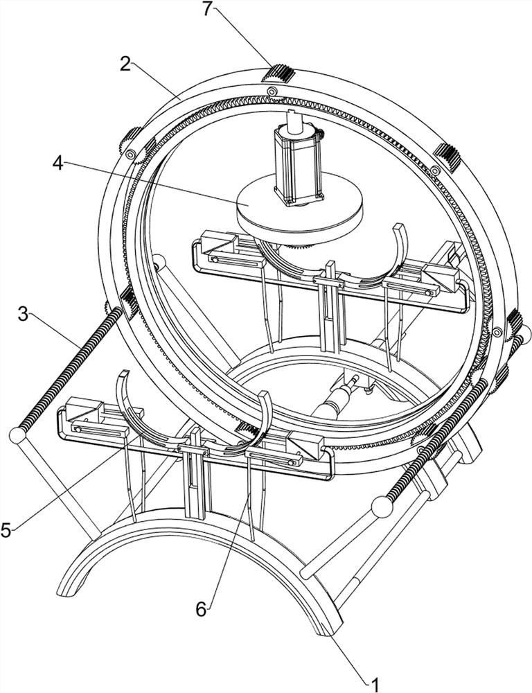
[0026] A steel pipe grinding and polishing equipment for building materials, such as figure 1 As shown, it includes a base 1, a pushing mechanism 2, a rotating mechanism 3, a grinding mechanism 4 and a positioning mechanism 5. The front side of the base 1 is provided with a pushing mechanism 2, and the base 1 is provided with a rotating mechanism 3. A polishing mechanism 4 is arranged on the side, and a positioning mechanism 5 is arranged on the top of the front and rear sides of the base 1 .
[0027] When people need to polish the steel pipe, they can use this steel pipe grinding and polishing equipment for building materials. First, people need to put the steel pipe on the positioning mechanism 5, and then start the pushing mechanism 2. After the pushing mechanism 2 is started, it will reciprocate back and forth , and then start the grinding mechanism 4, when the pushing mechanism 2 moves backwards and forwards, it drives the rotating mechanism 3 to rotate, so that the grind...
Embodiment 2
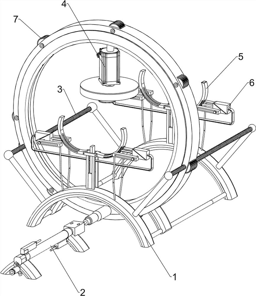
[0029] On the basis of Example 1, such as Figure 3-Figure 5 As shown, the pushing mechanism 2 includes a fixed seat 21, a cylinder 22, a movable seat 23 and an arc frame 24, and a cylinder 22 is installed between the fixed seats 21 on the front and rear sides, and the left and right sides of the base 1 are slidingly provided with a movable seat. 23, an arc frame 24 is arranged between the mobile seats 23 on both sides, and the lower side of the front part of the arc frame 24 is connected with the telescoping rod of the cylinder 22.
[0030] After the cylinder 22 starts, when the telescopic rod of the cylinder 22 pushes backward, the telescopic rod of the cylinder 22 drives the arc frame 24 on the moving seat 23 to move backward, and when the telescopic rod of the cylinder 22 pushes forward, the telescopic rod of the cylinder 22 moves backward. The telescoping rod drives the arc frame 24 to move forward and reset, so as to realize the effect of pushing without manually pushing...
PUM
 Abstract
Description
Claims
Application Information