
Assembly tool for miniature acceleration sensor

An acceleration sensor and assembly tooling technology, which is applied in metal processing, metal processing equipment, assembly machines, etc., can solve the problems of small parts size and complex assembly process, and achieve control of preload, assembly efficiency and product consistency. Effect of improving assembly work efficiency and range of use

Active Publication Date: 2021-04-13
GENERAL ENG RES INST CHINA ACAD OF ENG PHYSICS
View PDF11 Cites 3 Cited by
  • Summary
  • Abstract
  • Description
  • Claims
  • Application Information

AI Technical Summary

Problems solved by technology

For the miniature three-axis acceleration sensor, due to the small size of the parts, the assembly process relying on the traditional piezoelectric film adhesive method cannot meet the requirements. For the new sensor structure and working principle, it is necessary to carry out new process technology research and design new sensors. Assembly Tooling
[0003] For the traditional shear piezoelectric acceleration sensor, there are two main types of assembly processes: for larger-sized sensors, most of the piezoelectric sheets are assembled by viscose; for small-sized acceleration sensors, usually shape The method of shrinking and clamping the memory alloy to the piezoelectric ring requires the phase transformation of the memory alloy in a high temperature environment, and the assembly process is relatively complicated

Method used


Image

  • Assembly tool for miniature acceleration sensor
  • Assembly tool for miniature acceleration sensor
  • Assembly tool for miniature acceleration sensor

Examples


Embodiment Construction

[0035] The following will clearly and completely describe the technical solutions in the embodiments of the present invention with reference to the accompanying drawings in the embodiments of the present invention. Obviously, the described embodiments are only some, not all, embodiments of the present invention. Based on the embodiments of the present invention, all other embodiments obtained by persons of ordinary skill in the art without making creative efforts belong to the protection scope of the present invention.

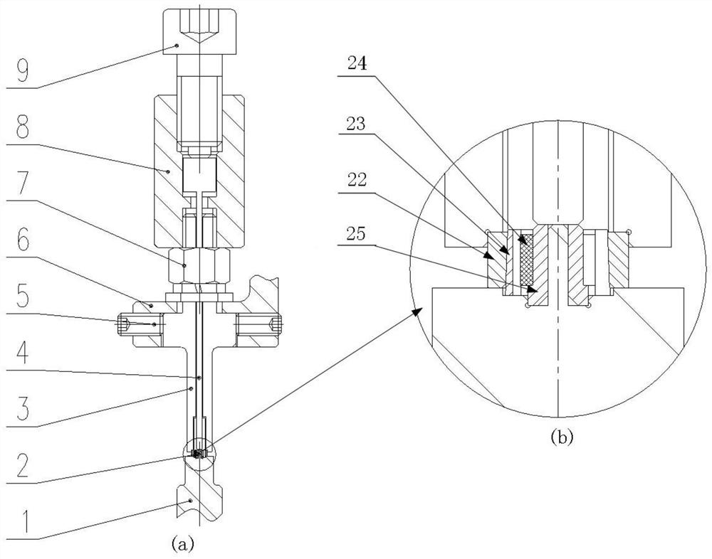
[0036] This application can be used as Figure 4 The assembly of a kind of acceleration sensor; Figure 4 Shown in the sensor base 21, the outer cone ring 22, the inner cone ring 23, the shear piezoelectric ring 24, the positioning ring 25, the central column 26;

[0037] The invention provides the following technical solutions:

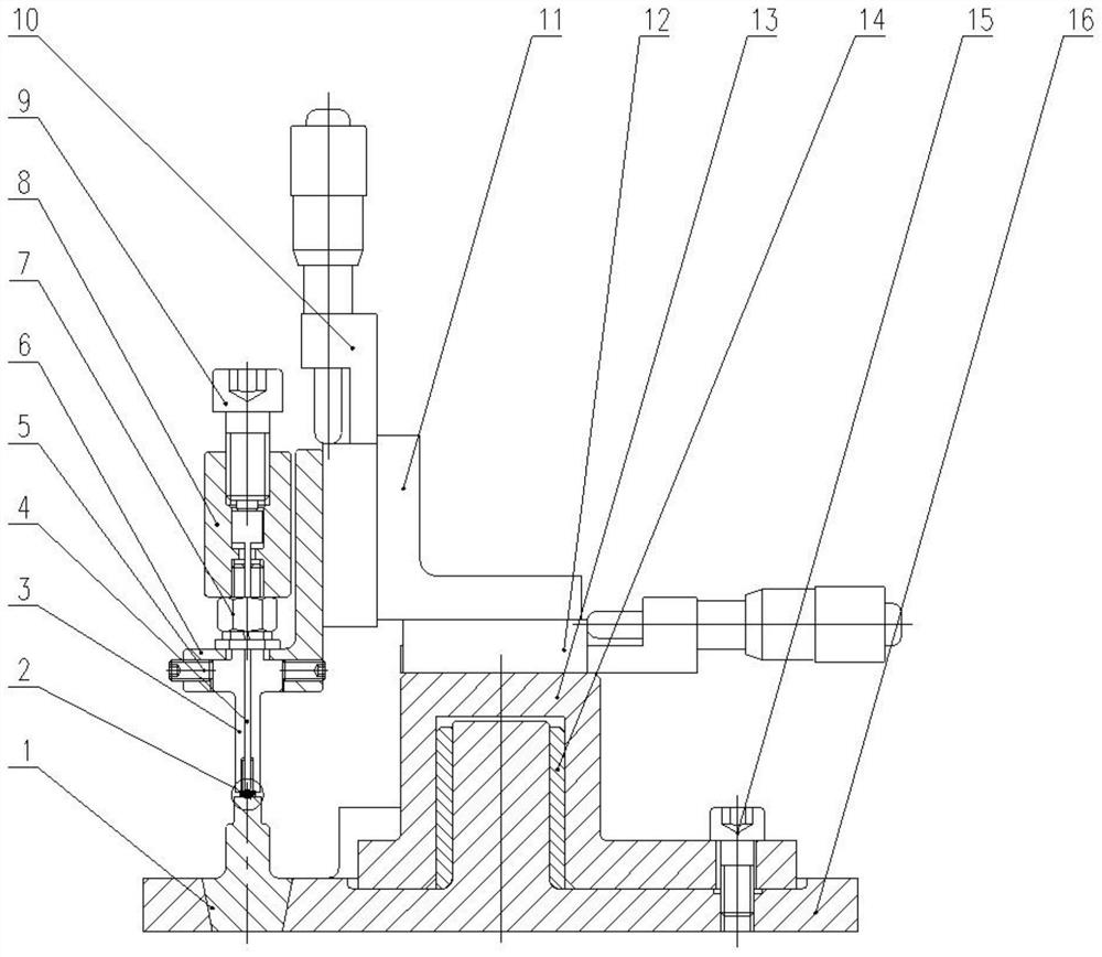
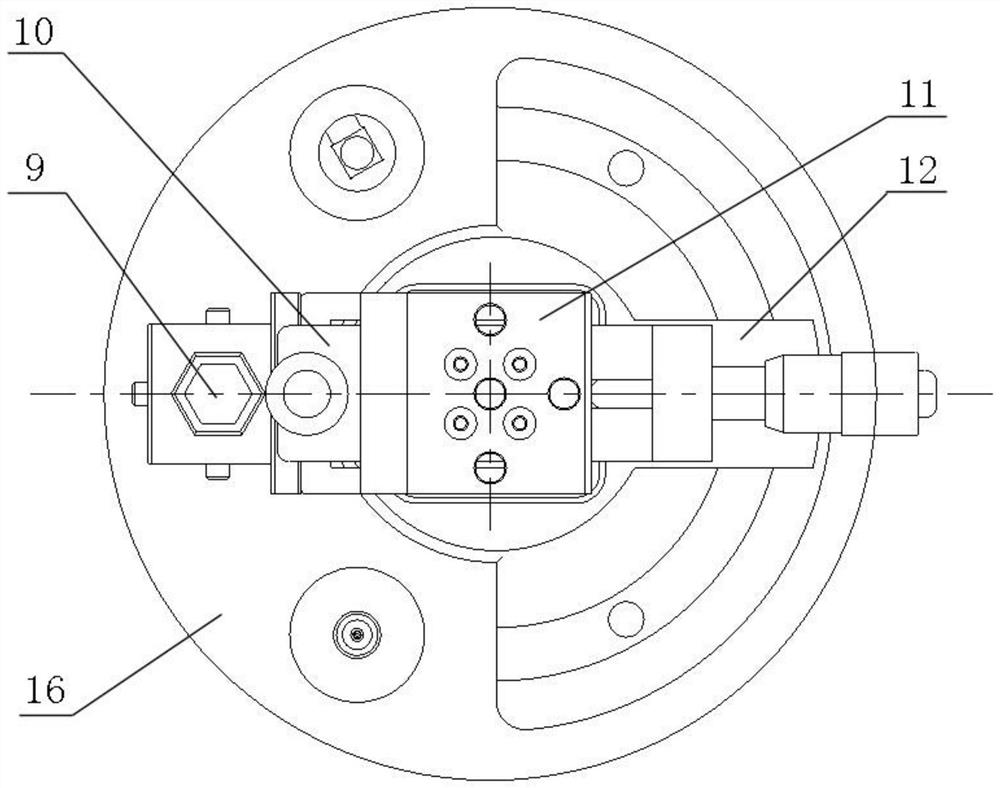
[0038] Such as Figure 1-3 As shown, an assembly tooling for a miniature acceleration sensor, including:

[0039] A multidirect...


PUM


Abstract

The invention discloses an assembly tool for a miniature acceleration sensor. The assembly tool comprises a multidirectional adjusting mechanism, a pressure head, a clamp and an ejector pin. The pressure head is connected with the adjusting end of the multidirectional adjusting mechanism; the first end of the pressure head is used for cooperating with the first end of the clamp to install the acceleration sensor; the mounting direction of the clamp is parallel to the second direction; a part of the acceleration sensor is positioned and placed at the first end of the clamp; a channel for the ejector pin to move is formed in the pressure head; and the ejector pin is movably arranged in the channel, and the first end of the ejector pin is matched with the first end of the clamp to install the acceleration sensor. According to the assembly tool, the clamp can be replaced, and is suitable for the assembly of various types of sensors. Under the condition that the clamp is not replaced, inner and outer conical rings, a piezoelectric patch and a positioning ring can be assembled, and the assembling efficiency and the product consistency are ensured; and the axial assembly size between the inner conical ring and the outer conical ring can be accurately controlled through a vertical fine adjustment platform, and therefore the pre-tightening force of the piezoelectric patch is effectively controlled.

Description

technical field [0001] The invention belongs to the technical field of acceleration sensors, and in particular relates to an assembly tool for a miniature acceleration sensor. Background technique [0002] The assembly process and production process of the sensor have a direct impact on the performance of the sensor. For the miniature three-axis acceleration sensor, due to the small size of the parts, the assembly process relying on the traditional piezoelectric film adhesive method cannot meet the requirements. For the new sensor structure and working principle, it is necessary to carry out new process technology research and design new sensors. Assembly tooling. [0003] For the traditional shear piezoelectric acceleration sensor, there are two main types of assembly processes: for larger-sized sensors, most of the piezoelectric sheets are assembled by viscose; for small-sized acceleration sensors, usually shape The method of shrinking and clamping the memory alloy to th...

Claims


Application Information

Patent Timeline
Patent Type & Authority Applications(China)
IPC IPC(8): B25B11/02B23P19/02B23P21/00
CPCB25B11/02B23P19/02B23P21/00
Inventor 程发斌王小龙张鹏朱昌亚韩海军陈川伍星
Owner GENERAL ENG RES INST CHINA ACAD OF ENG PHYSICS
Learn More