Exhaust pressure adjusting device

A technology of regulating device and exhaust pressure, applied in the direction of machine/engine, mechanical equipment, engine control, etc., can solve the problems of high motor temperature damage, short transmission distance, small internal space, etc., to achieve reliable work, easy connection, extension The effect of transmission distance

Pending Publication Date: 2021-04-13
GUANGZHOU AUTOMIBILE GRP MOTOR
View PDF11 Cites 0 Cited by
  • Summary
  • Abstract
  • Description
  • Claims
  • Application Information

AI Technical Summary

Problems solved by technology

[0005] In the existing schemes, the valve plate is arranged inside the valve body with a tubular structure, and the internal space is small. If the valve plate falls off and other failures occur, it is necessary to extend the hand into the pipe for operation, which makes maintenance more difficult; Or the motor installed on the transmission shaft has a relatively short transmission distance. Since the valve plate and the valve stem or the transmission shaft have been exposed to the high-temperature exhaust inside the exhaust valve body for a long time, the heat is transmitted to the output shaft of the motor through the valve stem or the transmission shaft. It is easy to cause damage to the motor due to overheating

Method used


Image

  • Exhaust pressure adjusting device
  • Exhaust pressure adjusting device
  • Exhaust pressure adjusting device

Examples


Embodiment 1

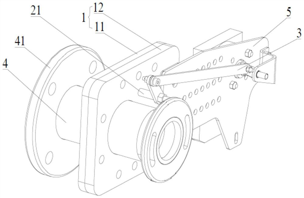
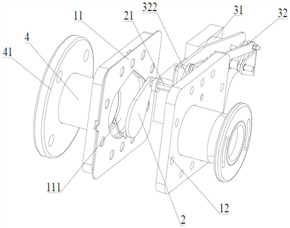
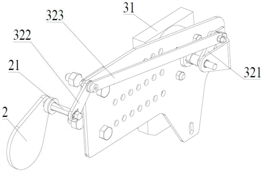
[0034] Such as Figure 1 to Figure 9 Shown is a first embodiment of an exhaust pressure regulating device, including a valve body 1, a valve plate 2 arranged inside the valve body 1, and a drive mechanism 3 connected to the valve plate 2; the valve The body 1 includes a detachably connected first valve body 11 and a second valve body 12, the first valve body 11 and the second valve body 12 communicate with each other and are provided with a smoke exhaust pipe 4; the first valve body 11 One end close to the second valve body 12 is also provided with a cavity 111 communicating with the smoke exhaust pipe 4, the valve plate 2 is movably arranged in the cavity 111, and the valve plate 2 is fixedly provided with A rotating shaft 21 , the rotating shaft 21 passes through the second valve body 12 and is in transmission connection with the driving mechanism 3 , and the valve plate 2 is driven by the driving mechanism 3 to rotate around the rotating shaft 21 .

[0035] It should be un...

Embodiment 2

[0046] Such as Figure 10 Shown is a second embodiment of an exhaust pressure regulating device. The difference between this embodiment and Embodiment 1 is that this embodiment also includes a fixing bracket 6, which is detachably connected to the first valve body 11. , the device is fixed by the fixing bracket 6, so as to avoid the vibration of the device caused by the rotation of the motor during the working process.


PUM


Abstract

The invention provides an exhaust pressure adjusting device. The exhaust pressure adjusting device comprises a valve body, a valve plate arranged in the valve body and a driving mechanism in transmission connection with the valve plate. The valve body comprises a first valve body and a second valve body which are detachably connected, and the first valve body and the second valve body are communicated and are both provided with smoke exhaust pipes in a communicating mode. A cavity communicating with the corresponding smoke exhaust pipe is further formed in the end, close to the second valve body, of the first valve body, the valve plate is movably arranged in the cavity, a rotating shaft is fixedly arranged on the valve plate, penetrates through the second valve body and is in transmission connection with the driving mechanism, and the valve plate is driven by the driving mechanism to rotate around the rotating shaft. The valve plate is arranged in the cavity of the first valve body, and meanwhile, the first valve body and the second valve body are detachably connected, so that the first valve body and the second valve body can be conveniently detached, and the valve plate inside can be replaced and maintained. Meanwhile, a connecting rod mechanism can prolong the transmission distance between a driving motor and the valve plate, increase heat dissipation and prevent the driving motor from being damaged due to over-high temperature.

Description

technical field [0001] The invention belongs to the technical field of engine bench tests, and more specifically relates to an exhaust pressure regulating device. Background technique [0002] During the engine running test, the exhaust back pressure of the engine has special requirements, and the corresponding maximum value of different models may be between 40 and 70KPa. Therefore, it is necessary to use the exhaust pressure regulating valve to adjust the opening of the exhaust pipe The degree of closure is used to adjust the engine exhaust back pressure. [0003] Most of the discharge pressure regulating valve structures currently used are butterfly valve structures, that is, the transmission shaft rotates around the axis, and then drives the valve plate fixed on the transmission shaft to also rotate around the axis of the transmission shaft. Among them, the upper part of the transmission shaft is connected with the motor or other driving structures, and is outside the e...

Claims


Application Information

Patent Timeline
Patent Type & Authority Applications(China)
IPC IPC(8): F02D9/10F02D11/10
CPCF02D9/10F02D9/101F02D9/1025F02D9/1065F02D11/10
Inventor 秦作鲲刘念李伟健
Owner GUANGZHOU AUTOMIBILE GRP MOTOR
Why Eureka
Try Eureka