Cast-in-place pile optical fiber monitoring system and method

A monitoring system and cast-in-place pile technology, which is applied to excavation, sheet pile walls, and measuring devices, can solve problems such as potential safety hazards in foundation pit construction, damage to optical fiber sensors, and failure to collect data, achieving small impact on the measurement environment and high monitoring efficiency Improve and monitor cost reduction effects

Pending Publication Date: 2021-04-13
中铁二十二局集团市政工程有限公司
View PDF0 Cites 6 Cited by
  • Summary
  • Abstract
  • Description
  • Claims
  • Application Information

AI Technical Summary

Problems solved by technology

However, in the embedding of optical fiber sensors, the optical fiber sensors are interfered by equipment and human factors, and there is a problem that the optical fiber sensors are seriously damaged. The survival rate of the optical fiber sensors is too low, resulting in failure to collect data during measurement, and it is difficult to install again after collection failure. The optical fiber sensor reduces the monitoring points of the foundation pit, and the monitoring data is greatly reduced, which leads to great safety hazards in the construction of the foundation pit
[0003] Due to the difficulties in power supply and signal transmission of optical fiber sensors in foundation pit monitoring, these sensors are currently working alone. Relevant status information, the obtained information is taken back to the laboratory for analysis, and then the results are obtained. This method cannot realize the function of networking and online monitoring and early warning, and the monitoring range is small
In addition, the optical fiber demodulation system is expensive. If each construction site needs to use this device to read data, the aging speed of the optical fiber demodulation system will be accelerated, affecting the service life, resulting in a substantial increase in the overall monitoring cost

Method used


Image

  • Cast-in-place pile optical fiber monitoring system and method
  • Cast-in-place pile optical fiber monitoring system and method
  • Cast-in-place pile optical fiber monitoring system and method

Examples


Embodiment Construction

[0038] The present invention will be described in further detail below in conjunction with the accompanying drawings and specific embodiments.

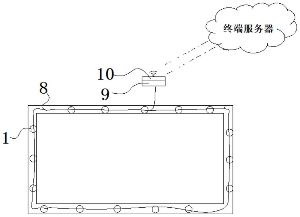
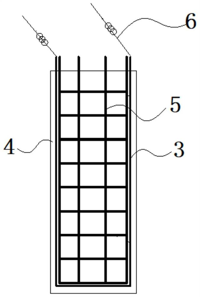
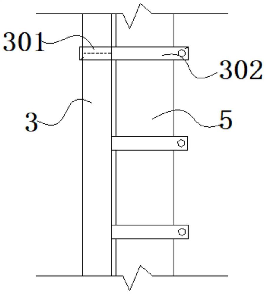
[0039] Such as Figure 1-6 As shown, the specific embodiment of the present invention is a fiber optic monitoring system for cast-in-situ piles. Each monitoring point 1 of cast-in-situ piles is equipped with an optical fiber sensor 2, and the optical fiber sensor 2 is installed on the cast-in-situ pile 4 through a protective fastener 3. The optical fiber sensor 2 is also connected to the main rib 5 of the optical fiber sensor 2 , and the optical fiber outgoing line 6 is connected to the detection module 7 . The optical fiber sensor is a fiber grating.

[0040] The protective fastener 3 includes a movable sleeve 301 and a buckle 302. The movable sleeve 301 is composed of a rotating shaft 303, a half-moon inner cover 304 and a half-moon outer cover 305. The half-moon outer cover 305 can rotate around the rotating shaft 303. open outsi...


PUM


Abstract

The invention discloses a cast-in-place pile optical fiber monitoring system. An optical fiber sensor is arranged in each cast-in-place pile monitoring point; each optical fiber sensor is arranged on a main reinforcement of a cast-in-place pile a through protection fastener; the optical fiber sensor is connected with an optical fiber outgoing line; and the optical fiber outgoing line is communicated with a detection module. The system realizes a foundation pit deformation automatic monitoring function, has the advantages of convenient measurement, high measurement efficiency, small influence of a measurement environment, real-time early warning and the like, realizes an intelligent measurement function, and enables measurement to be informationized; the protection fastener can effectively protect the optical fiber sensor and prevent the optical fiber sensor from being damaged by construction, and is high in practicability; and meanwhile, the foundation pit monitoring of each construction site is realized by one optical fiber demodulator, problems caused by the condition that optical fiber demodulators are few and are expensive are solved; and field technicians do not need to be additionally dispatched for monitoring, the management is convenient, the monitoring efficiency is greatly improved, and the monitoring cost is greatly reduced.

Description

technical field [0001] The invention relates to the field of safety detection equipment, in particular to an optical fiber monitoring system and method for cast-in-situ piles. Background technique [0002] In the process of foundation pit monitoring and early warning, because the environment of many points to be measured is complex and changeable, and this kind of detection needs to be carried out online for a long time, it requires sensors with strong anti-interference and corrosion resistance, and at the same time, it is necessary to send people on duty to monitor and measure Reading and recording data is time-consuming and labor-intensive. At present, optical fiber sensors have been used for monitoring and early warning of cast-in-place piles in foundation pits. However, in the embedding of optical fiber sensors, the optical fiber sensors are interfered by equipment and human factors, and there is a problem that the optical fiber sensors are seriously damaged. The surviv...

Claims


Application Information

Patent Timeline
Patent Type & Authority Applications(China)
IPC IPC(8): G01B11/16E02D33/00E02D17/02E02D5/34
CPCE02D5/34E02D17/02E02D33/00G01B11/18
Inventor 邓启智谢芳君吴红旗张彦伟胡志承蔡伟煌李会刘闯
Owner 中铁二十二局集团市政工程有限公司
Why Eureka
Try Eureka