
MIMO radar amplitude-phase error correction method

An amplitude-phase error and radar technology, which is applied in the field of MIMO radar amplitude-phase error correction, can solve the problems of inability to achieve precise positioning and high-resolution spatial spectrum estimation methods that cannot be used in practice, so as to improve global search capabilities, improve accuracy, and improve The effect of accuracy

Active Publication Date: 2021-04-13
ZHEJIANG UNIV
View PDF8 Cites 1 Cited by
  • Summary
  • Abstract
  • Description
  • Claims
  • Application Information

AI Technical Summary

Problems solved by technology

However, there are often many non-ideal factors in the multi-channel radar array system. The array errors of the transmitting and receiving channels will change the array manifold. When the array manifold cannot be accurately known, these direction-finding algorithms cannot achieve accurate positioning.
Therefore, array error estimation and correction is an important part of array signal processing. Without array error correction, any high-resolution spatial spectrum estimation method cannot be practically used.

Method used


Image

  • MIMO radar amplitude-phase error correction method
  • MIMO radar amplitude-phase error correction method
  • MIMO radar amplitude-phase error correction method

Examples


Embodiment Construction

[0045] The present invention will be described in detail below with reference to the accompanying drawings and preferred embodiments, and the purpose and effect of the present invention will become clearer. It should be understood that the specific embodiments described here are only used to explain the present invention and are not intended to limit the present invention.

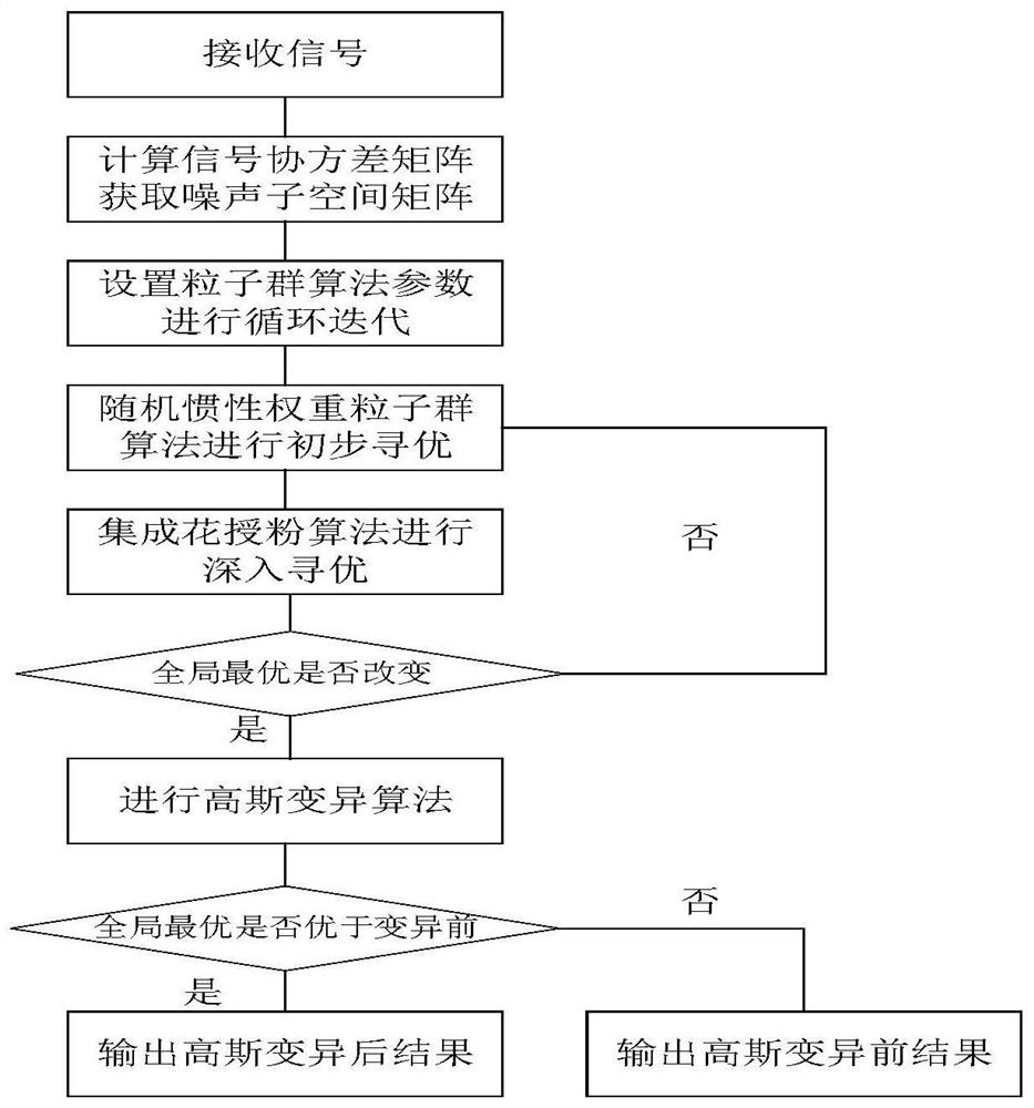
[0046] Such as figure 1 As shown, in the MIMO radar amplitude and phase error correction method of the present invention, the MIMO radar is a monostatic MIMO radar, and the uniform linear array of the MIMO radar has M transmit arrays and N receive arrays, and the transmit array and the receive array are placed along the y-axis; there are K different targets in space, and the reflected signals of different targets are independent of each other; the receiving end obtains MN virtual arrays; the tth pulse received by the receiving array is X(t), and There is a certain amplitude and phase error between the tran...


PUM


Abstract

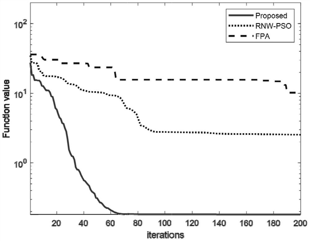
The invention discloses an MIMO radar amplitude-phase error correction method, which applies a particle swarm evolution algorithm to MIMO radar angle positioning and amplitude-phase error correction, and the defects that the particle swarm algorithm is easy to fall into local optimum and insufficient in search capability by introducing a flower pollination algorithm and a Gaussian mutation algorithm are overcome. Thus, the improved method can converge to the optimal result more quickly, an amplitude-phase error calibration matrix is obtained, and finally accurate angle positioning is achieved.

Description

technical field [0001] The invention relates to the field of MIMO radar signal processing, in particular to a method for correcting amplitude and phase errors of MIMO radar. Background technique [0002] The MIMO radar technology proposed in recent years can effectively increase the radar aperture and signal processing degrees of freedom, thereby improving the resolution and parameter estimation performance of spatial spectrum estimation. Therefore, the application of MIMO radar imaging to various workplaces such as unmanned driving technology, satellite positioning, and military target precision strikes has a good development prospect. [0003] Although the array spatial spectrum estimation algorithm has been verified in practical applications on many occasions, and achieved good results. However, there are often many non-ideal factors in the multi-channel radar array system. The array errors of the transmitting and receiving channels will change the array manifold. When t...

Claims


Application Information

Patent Timeline
IPC IPC(8): G01S13/02G01S7/41G01S7/40G06F17/16G06N3/00
CPCG01S13/02G01S7/418G01S7/40G06N3/006G06F17/16
Inventor 宋春毅姜自豪李俊杰徐志伟
Owner ZHEJIANG UNIV
Learn More