Transformer substation remote signal resetting device and method
A technology of remote signal and reset device, applied in the direction of electromagnetic relay details, circuits, relays, etc., can solve the problems of single design structure, frequent automatic reset, and inconvenient heat dissipation of the device
- Summary
- Abstract
- Description
- Claims
- Application Information
AI Technical Summary
Problems solved by technology
Method used
Image
Examples
Embodiment 1
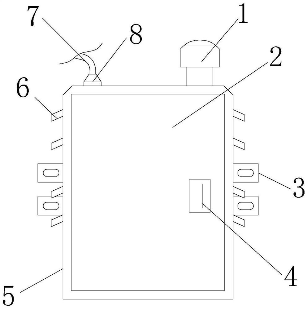
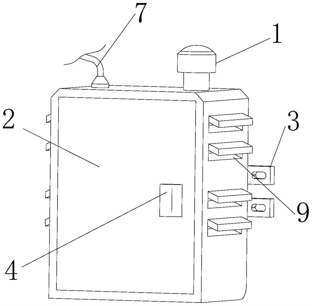
[0030] see Figure 1-7, the present invention provides a technical solution: a substation remote signal reset device, including a box body 5, a reset receiver 13 and an electromagnetic relay 15, the inner wall of the box body 5 is fixedly connected with a first support plate 22 and a second support plate 23 , the first support plate 22 is located above the second support plate 23, the top of the first support plate 22 is fixedly connected to the bottom of the reset receiver 13, the top of the second support plate 23 is fixedly connected to the bottom of the electromagnetic relay 15, and the electromagnetic relay The outer wall of 15 is electrically connected with the outer wall of the reset receiver 13 by being provided with a power line, and the outer wall of the electromagnetic relay 15 is electrically connected with the battery 14 through the provided power line, and the bottom of the battery 14 is fixedly connected with the top of the second support plate 23 The outer wall...
Embodiment 2
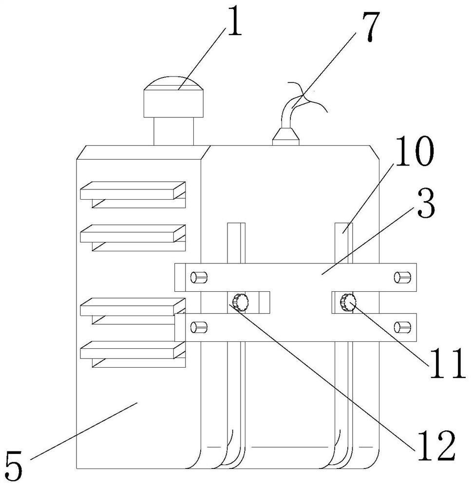
[0033] Such as Figure 1-7 As shown, on the basis of Embodiment 1, the present invention provides a technical solution: the outer wall of the box body 5 is movably connected with two first sliders 12, and the outer wall of the box body 5 is provided with a Matched T-shaped chute 10, the outer wall of each first slider 12 is fixedly connected with two pulleys 24 by being provided with a rotating shaft, each pulley 24 is located on the inner wall of T-shaped chute 10, and each first slider 12 The outer wall is fixedly connected with a fixed frame 3, the inner wall of the first slider 12 is threadedly connected with a bolt 11 by being provided with a thread groove, and the outer wall of the first slider 12 is movably connected with a brake block 25 through a concave hole, and the brake block 25 The outer wall is fixedly connected with the outer wall of the bolt 11.
[0034] In this embodiment, the first slider 12 is driven to slide on the inner wall of the T-shaped chute 10 by t...
Embodiment 3
[0036] Such as Figure 1-7 As shown, on the basis of Embodiment 1 and Embodiment 2, the present invention provides a technical solution: the outer wall of the box body 5 is provided with a plurality of cooling holes 9, and the top of each cooling hole 9 is fixedly connected with a baffle plate 6, The inner wall of the box body 5 is provided with a plurality of sliding grooves 19 , the inner wall of each sliding groove 19 is provided with a second sliding block 21 , and the other end of each second sliding block 21 is fixedly connected with a filter screen cover 20 .
[0037] In this embodiment, the flow of the wind is facilitated by a plurality of heat dissipation holes 9 provided, thereby cooling the device on the inner wall of the box body 5, and the setting of the baffle plate 6 cooperates with the setting of the inclination angle of the heat dissipation holes 9 to prevent water from flowing into the box body 5 Inner wall, the setting of filter screen cover 20, plays dust-p...
PUM
 Abstract
Description
Claims
Application Information
 - R&D
- Intellectual Property
- Life Sciences
- Materials
- Tech Scout
- Unparalleled Data Quality
- Higher Quality Content
- 60% Fewer Hallucinations
Browse by: Latest US Patents, China's latest patents, Technical Efficacy Thesaurus, Application Domain, Technology Topic, Popular Technical Reports.
© 2025 PatSnap. All rights reserved.Legal|Privacy policy|Modern Slavery Act Transparency Statement|Sitemap|About US| Contact US: help@patsnap.com


