Bus chamber structure of high-voltage miniaturized air-insulated switch cabinet

An air-insulated, cabinet bus room technology, applied in switchgear, switchgear setting, substation/switch layout details, etc., can solve the problems of inconvenient insulation strength and mechanical strength, inconvenience for long-term safe use, and difficulty in normal use of circuits, etc. Achieve good mechanical properties and anti-aging properties, easy for long-term safe use, and not easy to short circuit

Pending Publication Date: 2021-04-13
吉林德蕴电气集团股份有限公司
10 Cites 0 Cited by

AI-Extracted Technical Summary

Problems solved by technology

[0005] The purpose of the present invention is to provide a high-voltage miniaturized air-insulated switchgear busbar compartment structure to solve the problem of the general switchgear busbar compartment structure proposed in the above background technology, which is...

Abstract

The invention belongs to the technical field of switch cabinet bus chamber structures, and particularly relates to a bus chamber structure of a high-voltage miniaturized air insulation switch cabinet. The structure comprises a machine body and an air bellow, a bus area is installed on the outer side of the machine body, an installation plate is arranged on the outer wall of the bus area, and a bus sleeve is arranged on the outer side of the installation plate. A main bus is installed on the outer wall of the bus sleeve, a clamping groove is reserved in the outer wall of a damp-proof plate, a fixing block is fixed to the outer side of the clamping groove, a pressure relief channel is formed in the top of the fixing block, a spring is installed on the outer side of the pressure relief channel, a telescopic ladder is arranged on the outer wall of the spring, and a bottom plate is fixed to the bottom of the telescopic ladder. Compared with an existing switch cabinet bus chamber structure, the high-voltage miniaturized air insulation switch cabinet bus chamber structure guarantees higher insulation strength and mechanical strength of parts through structural optimization design, facilitates normal use of a circuit after insulation connection, is not prone to causing faults such as short circuit and the like, and facilitates long-term safe use.

Application Domain

Technology Topic

Image

  • Bus chamber structure of high-voltage miniaturized air-insulated switch cabinet
  • Bus chamber structure of high-voltage miniaturized air-insulated switch cabinet
  • Bus chamber structure of high-voltage miniaturized air-insulated switch cabinet

Examples

  • Experimental program(1)

Example Embodiment

[0023]Next, the technical solutions in the embodiments of the present invention will be apparent from the embodiment of the present invention, and it is clearly described, and it is understood that the described embodiments are merely embodiments of the present invention, not all of the embodiments. Based on the embodiments of the present invention, there are all other embodiments obtained without making creative labor without making creative labor premises.
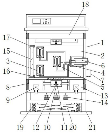
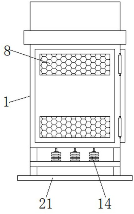
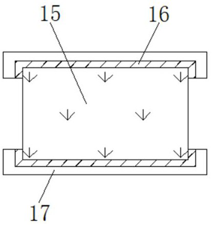
[0024]SeeFigure 1-5The present invention provides a technical solution: a high-pressure miniaturized air insulated switch cabinet shab chamber structure, including the body 1, the bus bar region 2, the mounting plate 3, the busbar sleeve 4, the main bus 5, the static contact head 6, current Incidental block 7, dust network 8, refrigeration block 9, bellow 10, bearing 11, air supply fan 12, cooling region 13, ground bus wire 14, moisture-proof plate 15, card slot 16, fixed block 17, pressure relief channel 18, spring 19 The outer side of the stretch plane 20 and the bottom plate 21, the outer wall of the body 1 are mounted, and the outer wall of the bus region 2 is provided with the mounting plate 3, and the outer side of the mounting plate 3 is provided with the bus casing 4, and the outer wall of the bus bar sleeve 4 is mounted. There is a main bus 5, and the right side of the main bus 5 is attached to the right side of the main bus 5, and the lower side of the static contact head block 6 is fixed, and there is a dust network 8 in the bottom of the current interacting block 7, and dust network The outer side of the 8 is provided with a refrigeration block 9, and the bellows 10 are mounted on the outer wall of the refrigeration block 9, and the bottom of the bellows 10 is connected to the bearing 11, and the bottom of the bearing 11 is attached, and the outer wall of the air exhaust fan 12 is provided with cooling. Region 13, the bottom portion of the cooling area 13 is fixed to the ground bus bar 14, and the outer side of the ground bus bar 14 is provided with a moisture-proof plate 15, and the outer wall of the moisture-proof plate 15 reserves the card slot 16, and the outer side of the card slot 16 is fixedly fixed. 17, The upper portion of the fixed block 17 is provided with a spring 19, and the outer wall of the pressure relief passage 18 is mounted, and the outer wall of the spring 19 is provided with a stretch lane 20, and the bottom plate 21 is fixed to the bottom of the stretch ladder 20.
[0025]Further, the main bus 5 constitutes an electrical connection by the static touch head block 6 and the current interacting block 7, and the main bus 5 and the bus casing 4 are integrated, such settings, the busbar sleeve 4 is the insulating material It succeeds that the main bus 5 is not only facilitated to effectively protect the effects, but also play a certain circuit insulation, it is not easy to cause a fault such as short circuit power failure in the circuit, easy to protect and long-term effective Normal control use of insulated switchgear;
[0026]Further, the ground bus wire 14 constitutes an electrical connection via the bus region 2 and the current interacting block 7, and the central axis of the ground bus wire 14 is combined with the central axis of the bottom plate 21, such settings, connecting the connection line of the current interacting block 7 and the ground The busbar 14 is connected, which ensures both the conductivity of the part and ensures mechanical strength. At the same time, the material in the insulating switchgear is good, electrical performance, mechanical properties and anti-aging performance are very good, through structural optimization Design, ensure that the insulation strength and mechanical strength of the part is more conducive to the normal use of the circuit after the insulated connection, it is not easy to cause a short circuit such as circuit short circuit, which is convenient for long-term safe use;
[0027]Further, the conductive fan 12 constitutes a rotation structure through the bearing 11 and the air box 10, and the air exhaust fan 12 is configured with respect to the center axis symmetry of the bus region 2, such a setting, the insulating switch cabinet bus area 2 is passed through the dust The network 8 is inhaled and inhaled, and then the start of the refrigeration block 9 will be refrigerated, and the gas inside the air box 10 will be refrigerated and cool, and the gas after the cooling temperature will be inhaled by the guide fan 12 and pass through The hole is discharged to the upper pressure relief passage 18 of the bus region 2, not only for air rapidly cooling and circulates into the bus region 2, but also easy to keep the insulation circuit wire in the bus bar area 2 in a suitable temperature. Preventing temperature over high pressure is excessively dangerous;
[0028]Further, the bus region 2 constitutes a gas flow cycle setting between the cooling regions 13 and the pressure relief channel 18, and the cooling area 13 and the refrigeration block 9 are engaged, such settings, the cyclic cold air is around the bus area 2 Always keep the insulation switching cabinet temperature in the normal range, and the hot air in the cabinet is passed through the air box 10 to pass the outside of the cabinet, and the heat gas in the insulating switchgear passes through the air supply fan 12 through the dust network 8. This completes the cooling operation of the insulated switchgear, so that the process of forming the airflow cycle is convenient to cool down the circuit electrical insulation switchgear in the use, ensuring the normal operation and circuit switching control management;
[0029]Further, the moisture-proof plate 15 constitutes a engagement structure through the card slot 16 and the fixing block 17, and the fixing block 17 and the body 1 are welded, such settings can be subjected to periodic disassembly to periodically replace the moisture-proof plate 15. This can effectively absorify moisture moisture in the cabinet, which is not easy to cause a circuit electrical component in the cabinet to affect its normal switch control, and the assembled installation is more portable and maintained in the insulated switchgear. Dry, It is not easy to damage the circuit or the like;
[0030]Further, the body 1 constitutes a lifting structure through the telescopic ladder 20 and the bottom plate 21, and the bottom plate 21 constitutes an elastic structure through the spring 19 and the body 1, such a setting, which is convenient for partial adjustment according to the actual use, and at the same time It will generate a certain shake, in order to ensure its normal stability, the spring 19 is provided on both sides of the stretchable ladder 20, and the elastic tract is used to stabilize the random ribroom, which is not easy to damage the switch cabinet bus chamber, which is easy to protect the protection and its long-term safety. use.
[0031]Working principle: When using this high-pressure miniaturized air insulated switch cabinet bus structure, first, when the body 1 is used in the use of the insulating switch bus chamber, by connecting the cable 5 on the main bus 5 and the static contact head 6, The current interactive block 7 constitutes a switch-controlled integral power system, and a bus bus casing 4 is provided on the main bus 5, the busbar sleeve 4 is made of insulating material, and its sleeve is not only easy to play in the main bus 5 not only. The role of protection has also played a certain circuit insulation. It is not easy to cause faults such as short circuit power failure in the circuit. Even if the protection is used to use the normal control of the insulated switchgear, and then insulated at the bus area 2. During the circuit of use, the connection line of the current interacting block 7 is connected to the ground bus wire 14, which ensures both the electrical conductivity of the part and ensures mechanical strength, and the material in the insulating switchgear is an epoxy resin. Electrical performance, mechanical properties and anti-aging properties are very good, through structural optimization design, ensure that the insulation strength and mechanical strength of the part is more conducive to the normal use of the circuit after the insulation connection, it is not easy to cause a short circuit such as circuit short circuit, which is easy to use for a long time. , Then by opening the total running switch in the insulating switchgear, the guide fan 12 in the bellows 10 is rotated, and the gas outside the insulating switch cabinet bus area 2 can be inhaled through the dust network 8 into the air and inhaled, and then After the start of the refrigeration block 9, the gas inside the guide fan 12 in the bellows 10 will be refrigerated and cool, and the gas after the cooling cooling is inhaled by the diamond piece 12 and discharged through the through hole to the bus area 2. The pressure passage 18 is not only facilitated airborne refrigeration and circulates into the bus region 2, but also easy to maintain the components of the insulation circuit wire in the bus bar area 2 in a suitable temperature, preventing temperature from excessive pressure from excessive danger. Then, the circulating cold air always keeps the insulating switch cabinet temperature in the normal range, and the heat gas in the cabinet is passed through the air box 10 to pass the outside of the cabinet, and the heat gas in the insulation switchgear passes through The air exhaust fan 12 is discharged by the upper dust network 8 to complete the cooling operation of the insulated switchgear, so that the process of forming the airflow cycle is convenient to cool down the circuit electrical insulation switchgear in the use, ensuring its normal operation. Management management with circuit switching;
[0032]Next, a moisture-proof plate 15 is provided in the insulating switchgear, and is connected to the fixed block 17, so that it can be disassembled for regular replacement of moisture-proof plate 15, which can be Effective moisture moisture moisture in the cabinet is not easy to cause the circuit electrical components in the cabinet to affect its normal switching control, and the assembled installation is more portable and maintains drying in the insulated switchgear, not easy to make circuits, etc. Damage, then damaged, then the extended ladder 20 in the bottom of the insulation switchgear is convenient for the height of the switchgear, which is convenient for partial adjustment according to the actual usage, and will have a certain amount of shaking at the same time, in order to ensure it is normal. Stable use, there is a spring 19 on both sides of the telescopic ladder, and the elastic tragene is used to stabilize the lifting operation, it is not easy to damage the switch cabinet bus chamber, which is easy to use for long-term safe use, which is the high-pressure miniaturizing air. The working principle of the insulated switch cabinet bus compartment structure.
[0033]While the embodiments of the invention have been shown and described, these examples may be made to make a variety of changes, modifications, and replacement without departing from the principles and spirit of the present invention, without departing from the spirit and spirit of the present invention. And variations, the scope of the invention is defined by the appended claims and their equivalents.

PUM

no PUM

Description & Claims & Application Information

We can also present the details of the Description, Claims and Application information to help users get a comprehensive understanding of the technical details of the patent, such as background art, summary of invention, brief description of drawings, description of embodiments, and other original content. On the other hand, users can also determine the specific scope of protection of the technology through the list of claims; as well as understand the changes in the life cycle of the technology with the presentation of the patent timeline. Login to view more.

Similar technology patents

Array substrate, manufacturing method and display panel

ActiveCN110707047ANot easy to short circuitImprove process yieldSolid-state devicesSemiconductor/solid-state device manufacturingPhysicsElectrically conductive
Owner:KUSN INFOVISION OPTOELECTRONICS

Solar cell module

InactiveCN106611801ANot easy to short circuitReduce insulationPhotovoltaic energy generationSemiconductor devicesSolar moduleSolar energy
Owner:ARCHERS

Radio-frequency coil capable of preventing short circuit

InactiveCN101191196ANot easy to short circuitVacuum evaporation coatingSputtering coatingRadio frequencyPhysical vapor deposition
Owner:SEMICON MFG INT (SHANGHAI) CORP

Classification and recommendation of technical efficacy words

  • Easy to protect
  • Not easy to short circuit

Rectifier diode, chip special for producing rectifier diode and producing method

ActiveCN1783516AAccelerateNot easy to short circuitSemiconductor/solid-state device manufacturingSemiconductor devicesBoron diffusionRectifier diodes
Owner:ANHUI PROVINCE QIMEN COUNTY HUANGSHAN ELECTRIC APPLIANCE

Water-based printed circuit board (PCB) cleaning agent and preparation method thereof

InactiveCN103540460AQuick ClearanceNot easy to short circuitSurface-active non-soap compounds and soap mixture detergentsIonFingerprint
Owner:合肥市华美光电科技有限公司

Array substrate, manufacturing method and display panel

ActiveCN110707047ANot easy to short circuitImprove process yieldSolid-state devicesSemiconductor/solid-state device manufacturingPhysicsElectrically conductive
Owner:KUSN INFOVISION OPTOELECTRONICS
Why Eureka
Try Eureka