Stirring device for pigment preparation

A stirring device and paint technology, which is applied to mixers with rotating stirring devices, mixer accessories, mixers, etc., can solve the problems of uneven manual stirring force, affecting the use feeling, and not being able to stir a large amount of paint at one time.

Pending Publication Date: 2021-04-16
黄爱武
View PDF9 Cites 0 Cited by
  • Summary
  • Abstract
  • Description
  • Claims
  • Application Information

AI Technical Summary

Problems solved by technology

[0004] In order to overcome the shortcomings of the manual mixing method relying on a hand-held mixer to stir it, the uneven force applied by manual mixing affects the feeling of use, and it cannot stir a large amount of pigments at one time. The technical problem is: to provide a machine to uniformly stir the pigments Guarantee the quality of the pigment, provide a larger container, and a stirring device for pigment production that can stir a large amount of pigment

Method used


Image

  • Stirring device for pigment preparation
  • Stirring device for pigment preparation
  • Stirring device for pigment preparation

Examples


Embodiment 1

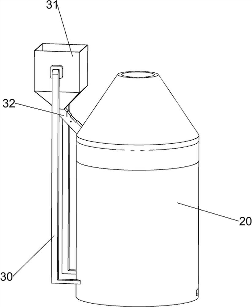
[0065] A stirring device for paint making, such as figure 1 As shown, it includes a base 1 , a stirring mechanism 2 and a feeding mechanism 3 , the stirring mechanism 2 is arranged on the top of the base 1 , and the feeding mechanism 3 is arranged on the left side of the stirring mechanism 2 .

[0066]The staff can place the paint in the feeding mechanism 3, and the paint will automatically slide into the stirring mechanism 2, and then start the stirring mechanism 2 to work to stir the paint. Pigments can be collected.

Embodiment 2

[0068] On the basis of Example 1, such as Figure 2 to Figure 5 As shown, the stirring mechanism 2 includes a stirring barrel 20, a first connecting block 21, a first servo motor 22 and a stirring rod 23, the top of the base 1 is slidingly provided with the stirring barrel 20, and the top of the stirring barrel 20 is provided with a first connecting block 21 , the top of the first connecting block 21 is provided with a first servo motor 22 , the bottom end of the output shaft of the first servo motor 22 is connected with a stirring rod 23 , and the stirring rod 23 is rotationally connected with the first connecting block 21 .

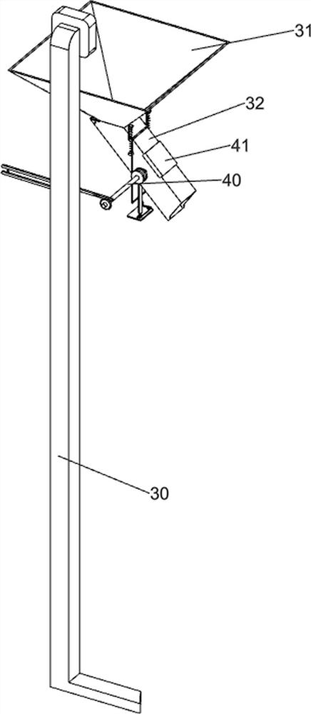
[0069] The blanking mechanism 3 includes a first connecting rod 30, a feed bin 31 and a feeding trough plate 32, the left side of the mixing bucket 20 is symmetrically connected with a first connecting rod 30, and the top of the first connecting rod 30 is connected with a feed bin 31, and the material The bottom of the warehouse 31 is connected with a f...

Embodiment 3

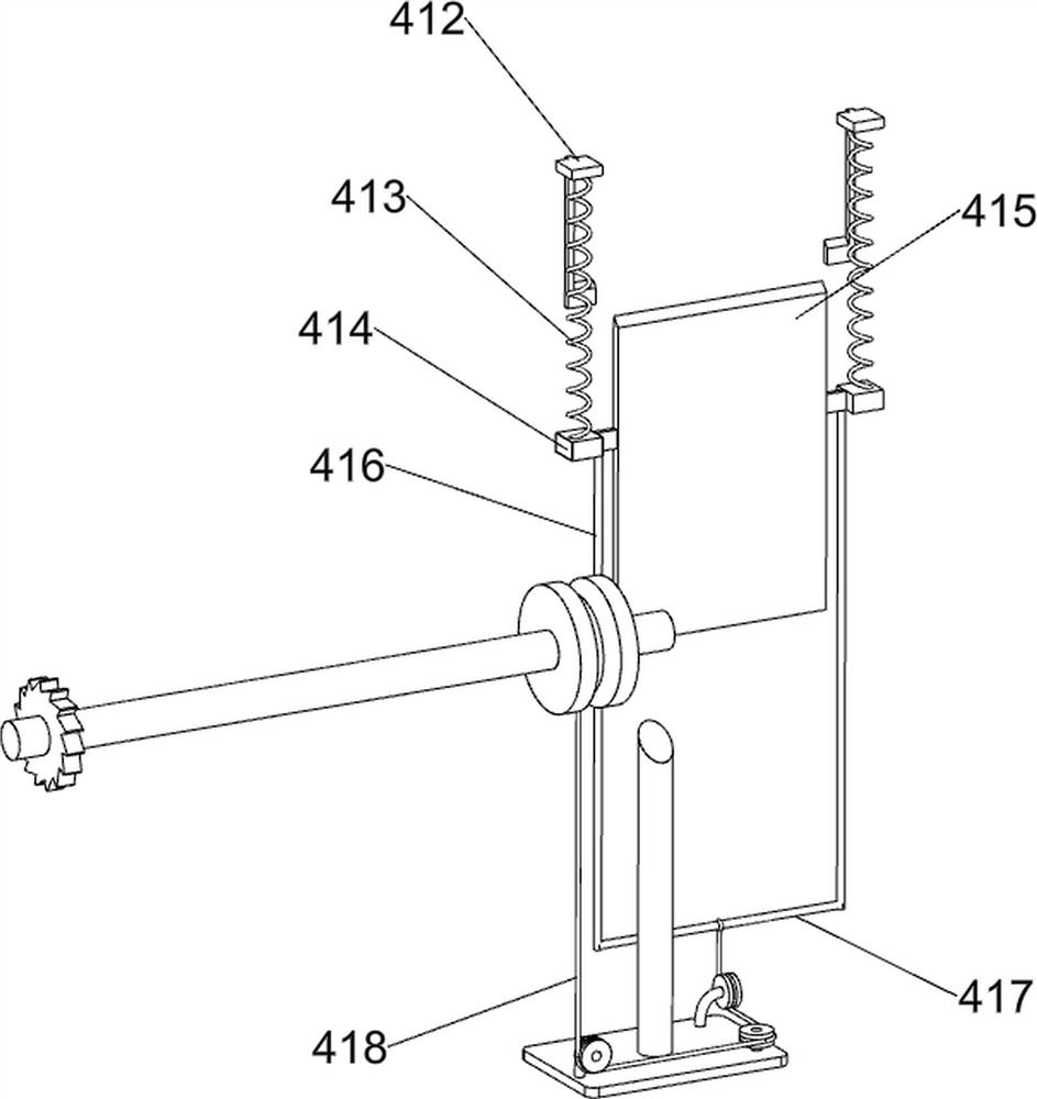
[0072] On the basis of Example 2, such as Figure 6 to Figure 13 As shown, the quantitative mechanism 4 is also included, and the quantitative mechanism 4 includes a rotating shaft 40, a first cover plate 41, a blade 42, a second connecting rod 43, a mounting table 44, a first pulley 45, a first fixed shaft 46, a second Pulley 47, second fixed shaft 48, third pulley 49, third fixed shaft 410, fourth pulley 411, second connecting block 412, first spring 413, third connecting block 414, first baffle plate 415, third Connecting rod 416, the 4th connecting rod 417, conveyer belt 418, the 5th connecting rod 419, ratchet 420, the second spring 421 and ratchet 422, the rotating shaft 40 is connected with the middle part of cutting trough plate 32, is connected with the 4th rotating shaft 40. A pulley 45, the rear side of the rotating shaft 40 is connected with a blade 42, the blade 42 is located in the lower chute plate 32, the top right side of the lower chute plate 32 is connected ...


PUM


Abstract

The invention relates to a stirring device, in particular to a stirring device for pigment manufacturing, and mainly provides the stirring device for pigment manufacturing, which is used for uniformly stirring pigment by a machine, ensuring the quality of the pigment, providing a larger container and stirring a large amount of pigment. The stirring device for pigment manufacturing comprises a base, a stirring mechanism, a driving mechanism and a driving mechanism, and a discharging mechanism, which is arranged on one side of the stirring mechanism and is arranged to control discharging, so that pigment is conveniently placed in the stirring barrel to be matched with stirring; by arranging a first cover plate and an observation mechanism, the discharging condition of the pigment is observed, and the situation that excessive pigment is placed to influence stirring is prevented.

Description

technical field [0001] The invention relates to a stirring device, in particular to a stirring device for making pigments. Background technique [0002] Pigment is a substance that can dye objects with color. Generally, a certain amount of liquid and pigment powder are used for stirring, and the stirred pigment is in a fluid state. [0003] The traditional mixing method relies on manually pouring a certain proportion of liquid and pigment powder into the same container, and then mixing it with a hand-held mixer. The uneven force of manual mixing will affect the use and appearance of the pigment. Therefore, most manufacturers focus on the use efficiency. The higher stirring machine is used to stir the paint. The stirring machine is composed of a mixing barrel and a stirring rod. The stirring rod is driven by electricity to rotate at a high speed to stir the paint. Although this method is efficient, the height of the stirring rod is fixed and the material deposited at the bott...

Claims


Application Information

Patent Timeline
IPC IPC(8): B01F15/00B01F7/18B01F15/02
Inventor 黄爱武
Owner 黄爱武
Why Eureka
Try Eureka