
Automatic real stone paint production equipment

A kind of production equipment and technology of real stone paint, applied in the field of real stone paint, can solve the problem of high cost and achieve the effect of reducing production cost

Inactive Publication Date: 2021-04-16
WUXI LEHUA AUTOMATION TECH
View PDF7 Cites 1 Cited by
  • Summary
  • Abstract
  • Description
  • Claims
  • Application Information

AI Technical Summary

Problems solved by technology

[0004] The purpose of the present invention is to solve the disadvantages in the prior art that when producing real stone paint, the natural granite, natural crushed stone, stone powder and other sand and gravel are usually purchased as raw materials, resulting in relatively high cost, and an automatic real stone paint is proposed. Lacquer production equipment

Method used


Image

  • Automatic real stone paint production equipment
  • Automatic real stone paint production equipment
  • Automatic real stone paint production equipment

Examples


Embodiment 1

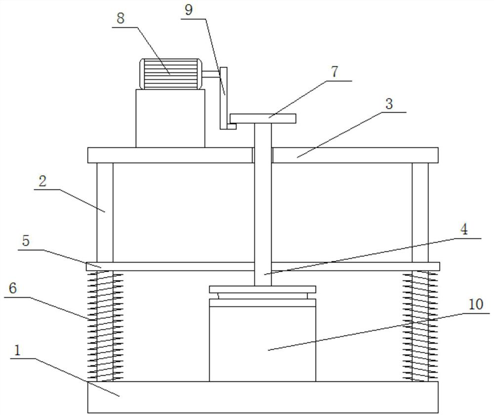
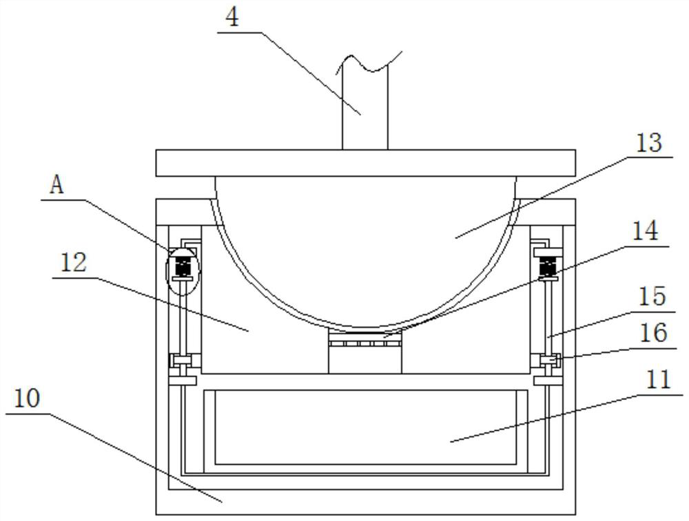
[0023] refer to Figure 1-5 , an automatic real stone paint production equipment, including a base 1, two uprights 2 are symmetrically and fixedly installed on the top of the base 1, and the same horizontal plate 3 is fixedly installed on the top of the two uprights 2, and the horizontal plate 3 is slidably connected with a connection Rod 4, the bottom end of connecting rod 4 extends to the below of horizontal plate 3 and is fixedly installed with hammer head 13, and the top of base 1 is fixedly installed with processing box 10, and is slidingly connected with placing seat 12 in processing box 10, and placing seat 12 The top is provided with a spherical groove, and the bottom of the hammer head 13 extends into the spherical groove, and the bottom inner wall of the spherical groove is provided with a feeding hole, and a screen 14 is fixedly installed in the feeding hole, and the bottom of the screen 14 A steel bar grid is fixedly installed, and the steel bar grid is fixedly con...

Embodiment 2

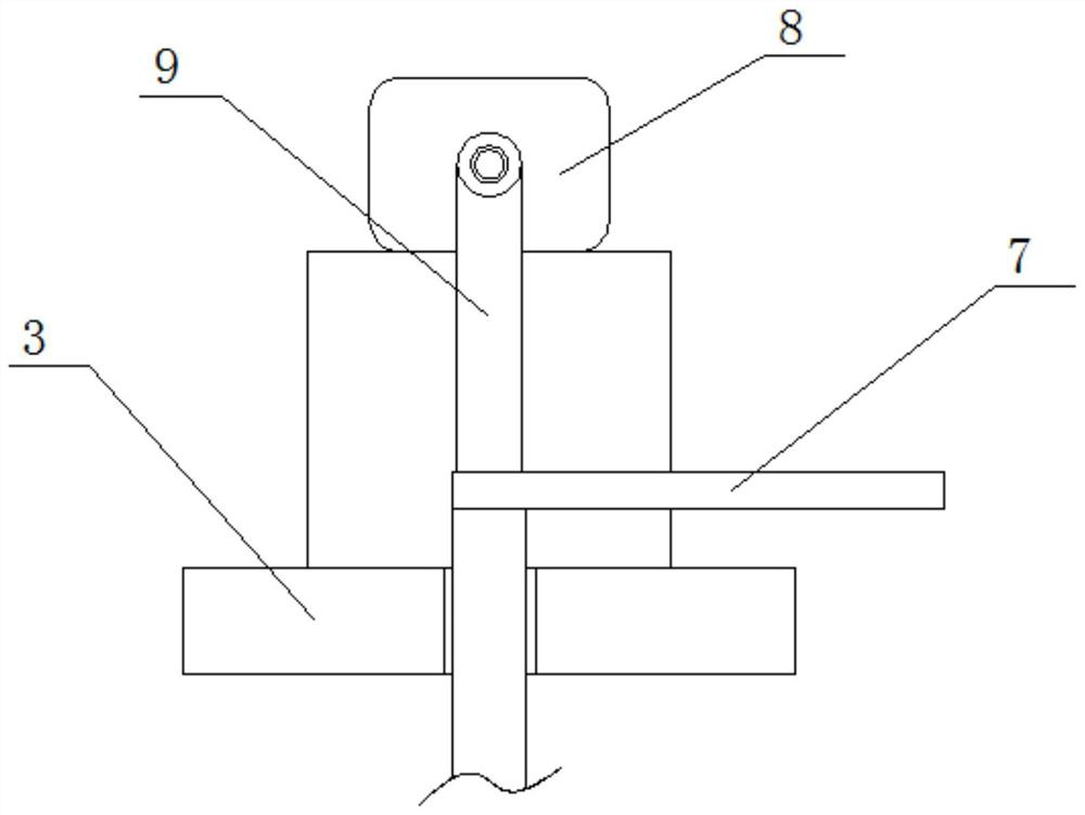
[0025] In the present invention, a rotating rod 9 is fixedly installed on the output shaft of the driving motor 8, and a lifting shaft is fixedly installed at the bottom of one side of the rotating rod 9, and the top of the connecting rod 4 extends to the top of the horizontal plate 3 and is fixedly installed with a connecting plate 7 , the lifting shaft is in movable contact with the bottom side of the connecting plate 7, and the lifting shaft is movably connected with the connecting plate 7 to facilitate driving the hammer head 13 to perform free fall motion.

[0026] In the present invention, the limit rod 5 is slidably connected to the column 2, and one end of the two limit rods 5 close to each other is fixedly connected to the connecting rod 4, and the column 2 is sleeved with a tension spring 6, and the tension spring 6 is located at Below the limiting rod 5, the top and bottom ends of the tension spring 6 are fixedly connected with the bottom of the limiting rod 5 and th...


PUM


Abstract

The invention belongs to the field of real stone paint, particularly relates to automatic real stone paint production equipment, and aims to solve the problem that the cost is high as finished natural granite, natural gravel, stone powder and other kinds of gravel are generally purchased as raw materials during existing real stone paint production. According to the scheme, the automatic real stone paint production equipment comprises a base, wherein two stand columns are symmetrically and fixedly mounted at the top of the base, the same transverse plate is fixedly mounted at the top ends of the two stand columns, and a connecting rod is slidably connected to the transverse plate. According to the automatic real stone paint production equipment, a hammer head can be driven to fall multiple times by starting a driving motor, so that excess materials can be impacted, and the excess materials can be effectively crushed; the crushed particles can be filtered by using a screen, so that real stone paint particles with uniform sizes can be obtained; and meanwhile, raw materials can be purchased in the mode of purchasing excess materials and waste materials, so that the production cost can be greatly reduced.

Description

technical field [0001] The invention relates to the technical field of real stone paint, in particular to an automatic real stone paint production equipment. Background technique [0002] Real stone paint is a coating formulated with natural granite, natural gravel, stone powder, etc. as the main materials, with synthetic resin emulsion as the main binder and supplemented with various additives. The spraying effect of real stone paint is solemn and elegant, which can fully show the rich texture of natural stone. Real stone paint has strong adhesion, high hardness, rich texture, economical cost, and good weather resistance. It has the advantages of fire prevention, fire prevention, acid and alkali resistance, pollution resistance and non-toxicity; [0003] Nowadays, in the production of real stone paint, it is generally purchased finished natural granite, natural gravel, stone powder and other sand and gravel as raw materials, resulting in relatively high costs. However, wh...

Claims


Application Information

Patent Timeline
IPC IPC(8): B02C1/14B02C23/16
Inventor 钱国东
Owner WUXI LEHUA AUTOMATION TECH
Learn More