Automatic workpiece punching device

An automatic punching and workpiece technology, which is applied in the field of workpiece punching, can solve the problems of inconvenient workpiece utilization, inability to burr, burr grinding, shortening the punching operation cycle, etc., and achieve the effects of energy saving, efficiency improvement, and shortened construction period

Active Publication Date: 2021-04-16
SHAOXING UNIV YUANPEI COLLEGE
View PDF7 Cites 5 Cited by
  • Summary
  • Abstract
  • Description
  • Claims
  • Application Information

AI Technical Summary

Problems solved by technology

[0005] In order to overcome the technical problem that the punching device in the prior art cannot grind the burrs and burrs at the penetration of the hole, which is not convenient for the later use of the workpiece, the present invention provides an automatic punching device for the workpiece. It can automatically grind the burrs and burrs at the hole penetration. Compared with the step-by-step processing method of punching and then grinding in the traditional operation, this application integrates the punching operation and the grinding operation, which greatly shortens the punching time. The machining cycle of the hole operation is shortened, thereby effectively improving the machining efficiency

Method used


Image

  • Automatic workpiece punching device
  • Automatic workpiece punching device
  • Automatic workpiece punching device

Examples


Embodiment

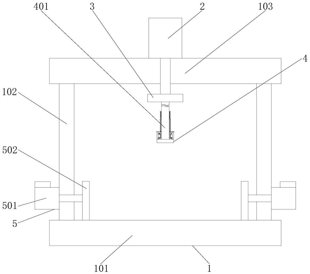
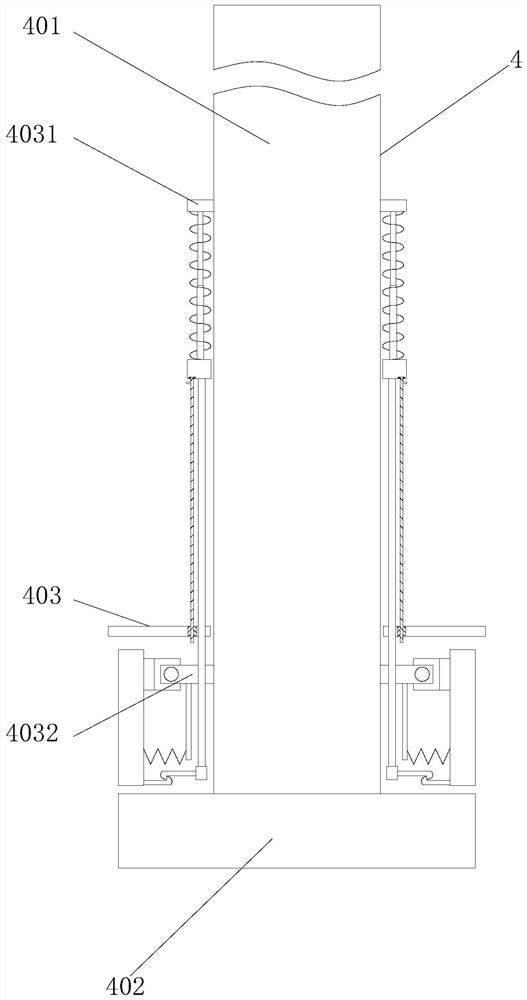
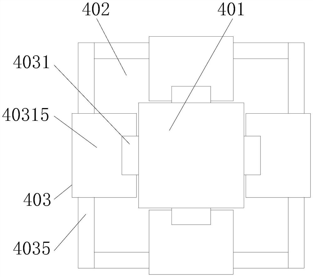
[0033] Such as Figure 1-Figure 7 As shown, the present invention provides a kind of workpiece automatic punching device, comprises frame 1, hydraulic cylinder 2, moving plate 3 and punching head 4, and hydraulic cylinder 2 is fixedly installed on the frame 1, and the setting of hydraulic cylinder 2 is for Drive the moving plate 3 to move up and down, the moving plate 3 is fixedly connected to the output end of the bottom of the hydraulic cylinder 2, the punching head 4 is fixedly installed on the bottom of the moving plate 3, the frame 1 includes a base plate 101, the left and right sides of the top of the base plate 101 Both vertical plates 102 are fixedly connected, the tops of the two vertical plates 102 are fixedly connected by the top plate 103, the hydraulic cylinder 2 is fixedly installed on the top of the top plate 103, and the side of the vertical plate 102 away from the punching head 4 is fixedly installed with a clamping mechanism 5 The clamping mechanism 5 include...


PUM


Abstract

The invention provides an automatic workpiece punching device to solve the technical problems that in the prior art, a punching device cannot carry out polishing treatment on burrs, flashes and the like at the penetrating position of a hole, and later workpiece utilization is inconvenient. The automatic workpiece punching device comprises a rack, wherein the rack comprises a bottom plate and a top plate which are arranged at an interval; a punching head is arranged on the top plate; a clamping mechanism for limiting a workpiece is arranged on the bottom plate; the punching head comprises a punching punch and a hydraulic cylinder; a connecting rod is arranged between the punching punch and the hydraulic cylinder; a plurality of auxiliary mechanisms are arranged in the circumferential direction of the connecting rod; and each auxiliary mechanism comprises a reset part, an adjusting part and a friction part, each adjusting part comprises a stabilizing block with one end connected with the connecting rod, each friction part comprises a friction plate with one end rotationally connected with the other end of the stabilizing block, one end of each reset part is connected with one friction plate, the other end of each reset part is connected with one adjusting part, the outer side surface of each friction plate is flush with the circumferential surface of the punching punch when the corresponding reset part is compressed, and each friction plate partially protrudes out of the circumferential surface of the punching punch when the corresponding reset part extends.

Description

technical field [0001] The invention relates to the technical field of workpiece punching, in particular to an automatic workpiece punching device. Background technique [0002] Punching refers to punching various graphics on steel plates, leather, cloth, wood and other materials to meet different needs. When punching workpieces, punching devices are required. The existing automatic punching devices for workpieces cannot The burrs and burrs at the place are processed, and workers need to rework later. [0003] The notification number is CN104923614A, a punching device with photographic detection and positioning, including a punching driving device, an upper template and a punching head, and also includes a clamping device and a support seat located below the punching head, and the clamping device It includes symmetrically arranged clamping blocks, and the workpiece is clamped between the clamping blocks; a camera positioning device is provided between the upper template and...

Claims


Application Information

Patent Timeline
Patent Type & Authority Applications(China)
IPC IPC(8): B23P23/04B21D28/34B21D28/04B24B9/00B26F1/14B26D7/02
Inventor 潘慧
Owner SHAOXING UNIV YUANPEI COLLEGE
Why Eureka
Try Eureka