Grinding mechanism of common lathe

A technology of grinding mechanism and common lathe, applied in grinding machine, abrasive belt grinder, grinding/polishing equipment, etc., can solve the problems of reduced abrasive belt grinding effect, difficulty in guaranteeing workpiece grinding effect, etc., and achieve the effect of guaranteeing the limit effect

Active Publication Date: 2021-04-16
上海易新冶金设备制造有限公司
View PDF7 Cites 2 Cited by
  • Summary
  • Abstract
  • Description
  • Claims
  • Application Information

AI Technical Summary

Problems solved by technology

[0004] In view of the above-mentioned related technologies, the inventor believes that due to the long shaft workpiece, during the grinding process of the workpiece by the abrasive belt, the ore on the surface of the abrasive belt will be worn during the grinding work, and the abrasive belt itself will gradually lose its elasticity. effect, so as the grinding work progresses, the contact force between the abrasive belt and the workpiece gradually decreases, resulting in a gradual decrease in the grinding effect of the abrasive belt on the workpiece, making it difficult to ensure the grinding effect of the workpiece

Method used


Image

  • Grinding mechanism of common lathe
  • Grinding mechanism of common lathe
  • Grinding mechanism of common lathe

Examples


Embodiment 1

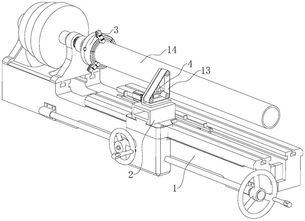
[0036] The embodiment of the present application discloses a grinding mechanism of an ordinary lathe, referring to figure 1 and 2, comprising a bracket 4 installed on the tool table seat 2, the bracket 4 is arranged in a triangle, and one end facing the workpiece 14 is an opening; the three corners of the bracket 4 are respectively rotated to connect the driving wheel 5, the driven wheel 6, and the tensioning wheel 7. The driving wheel 5 is set on the side away from the opening of the support 4; the driving wheel 5, the driven wheel 6 and the tension wheel 7 are covered with the same abrasive belt 13; the support 4 is also fixed with a motor 10, and the output shaft of the motor 10 is connected to the The driving wheel 5 is coaxially fixed and communicated with an external power supply through a power cord. In the present embodiment, it is mainly used for grinding the slender shaft workpiece 14; the workpiece 14 is fixed on the clamping mechanism 3 of the lathe and rotates, t...

Embodiment 2

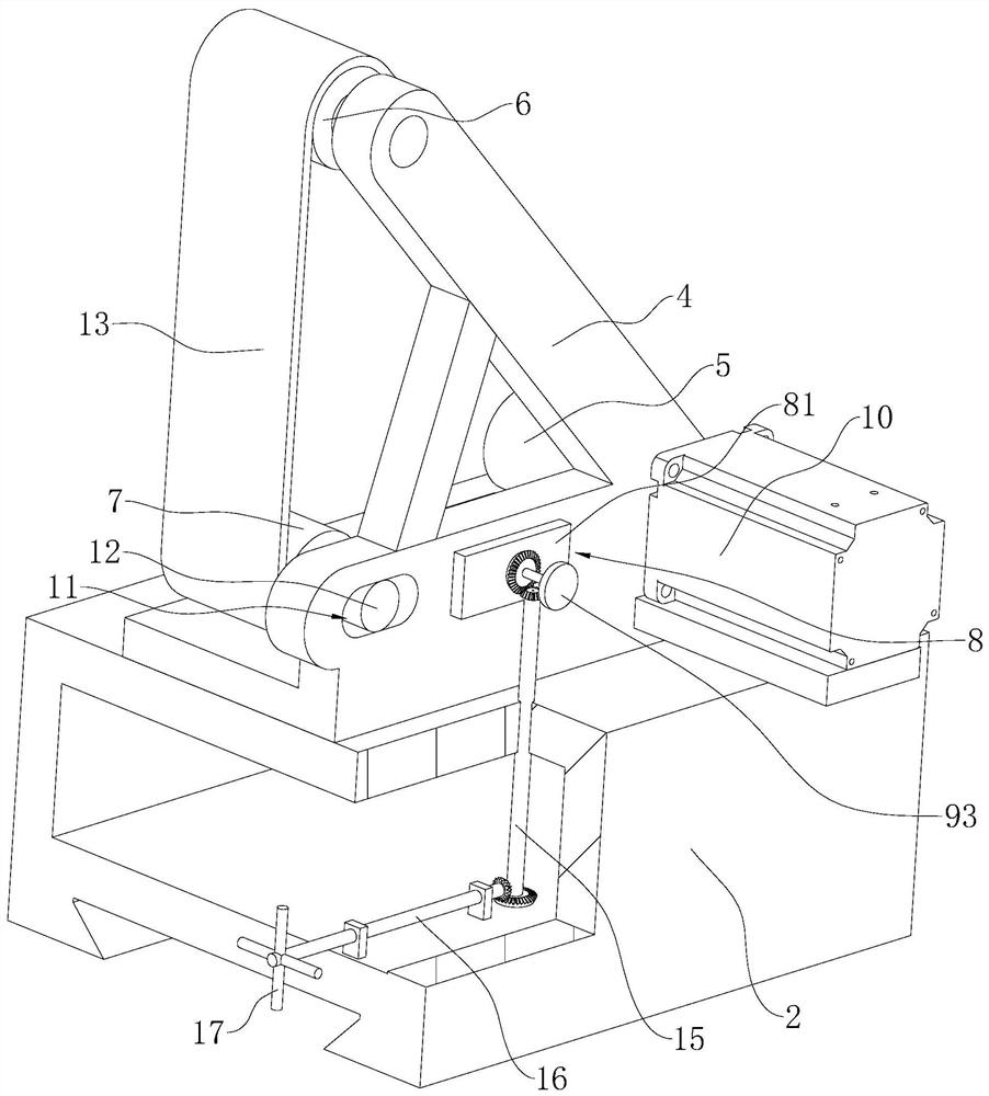
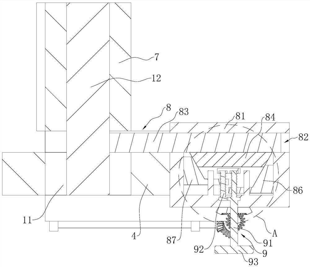
[0043] refer to figure 1 with 5 , the difference from Embodiment 1 is that the lathe base 1 is provided with a guide mechanism 18 along its length direction and below the workpiece 14; refer to figure 2 with 5 : Simultaneously screw rod one 91 is in one section outside mounting seat 81 and is connected with connecting shaft mechanism; Connecting rod mechanism comprises connecting rod one 15 and connecting rod two 16, and connecting rod one 15 is vertically arranged, and bevel gear one is fixed on the upper end, and screw Rod one 91 is coaxially fixed with bevel gear two meshing with bevel gear one to realize the transmission between connecting rod one 15 and screw mandrel one 91; the other end of connecting rod one 15 is coaxially fixed with bevel gear three and connecting rod two 16 One end is fixed with the bevel gear 4 meshing with the bevel gear 3, and the connecting rod 2 16 is arranged vertically to the moving direction of the tool pedestal 2, and the connecting rod 2...


PUM


Abstract

The invention relates to a grinding mechanism of a common lathe. The grinding mechanism comprises a support arranged on a cutter pedestal, wherein a driving wheel and a driven wheel are rotationally connected to the support, and a motor connected with the driving wheel is arranged on the support; an abrasive belt is connected to the exterior of the driving wheel and the exterior of the driven wheel in a sleeving mode; a tensioning wheel is rotationally connected to the support, the outer wall of the tensioning wheel abuts against the abrasive belt, and the tensioning wheel is rotationally connected with a rotating shaft; a sliding groove for the rotating shaft to penetrate through and slide is formed in the support; and a transmission piece for driving the rotating shaft to slide is arranged on the support. The grinding mechanism has the effects that the grinding effect on a workpiece is improved, and the quality of the produced workpiece is guaranteed.

Description

technical field [0001] The present application relates to the field of mechanical processing, in particular to a grinding mechanism of a common lathe. Background technique [0002] When using a lathe to process a long shaft workpiece, the turning tool of an ordinary lathe cannot guarantee the precise machining of the surface roughness of the shaft workpiece. [0003] The Chinese patent with the authorized notification number CN207415057U discloses a special grinding device for ordinary lathes, including a motor, a knife base, a grinding wheel, an abrasive belt and a pretensioner wheel. The motor is installed on the knife base, and the output shaft of the motor is fixed to the grinding wheel. , the abrasive belt is set on the pre-tension wheel and the grinding wheel, the abrasive belt touches the workpiece, the motor drives the grinding wheel to rotate, and then drives the abrasive belt to rotate, and the workpiece is polished. [0004] In view of the above-mentioned related...

Claims


Application Information

Patent Timeline
Patent Type & Authority Applications(China)
IPC IPC(8): B24B21/00B24B21/20
Inventor 洪增勤
Owner 上海易新冶金设备制造有限公司
Why Eureka
Try Eureka