Rubber preforming device

A pre-forming, rubber technology, applied in the field of rubber manufacturing, can solve the problems of weight difference of rubber blocks, poor cutting effect of a single cutter, troublesome use, etc., to achieve the effect of speeding up the cooling rate, convenient and fast precise cutting

Inactive Publication Date: 2021-04-16
ZHEJIANG TIANTAI XIANGHE IND CO LTD
View PDF6 Cites 2 Cited by
  • Summary
  • Abstract
  • Description
  • Claims
  • Application Information

AI Technical Summary

Problems solved by technology

[0002] In the rubber preforming machine in the prior art, when the rubber is preformed, a hydraulic device is usually used to extrude the high-temperature rubber into strips, and cut it into a specified size by a cutter, which is convenient for subsequent vulcanization and molding. However, due to the high temperature and soft texture of the rubber itself during the extrusion process, the rubber itself is easy to adhere to the cutter when cutting. At the same time, due to its soft texture, the cut surface will There is a certain deformation, which leads to a certain difference in the weight of the cut rubber block. At the same time, most of the cutting knives in the prior art need to be driven by a cutting motor to cut the rubber strip through high-speed rotation. The high-speed rotating cutter needs to be equipped with a protective cover. , there are certain hidden dangers in operation, and it is more troublesome to use
[0003] The rubber model preforming machine cutting device released by Chinese patent, application number: 2011202260819, comprises a cutter motor, a speed change mechanism, a triangle support frame, a flywheel shaft, a cutter, a frame and a transport device. On the head of the model preforming machine, the transportation device is installed at the lower part of the frame. Compared with the prior art, this utility model has a simpler structure, more complete functions, and it is convenient to adjust the distance between the cutters and the cutting speed. Driven by the flywheel shaft to rotate at high speed, there are certain safety hazards in use, and when cutting, the cutting effect of a single cutter is poor

Method used


Image

  • Rubber preforming device
  • Rubber preforming device
  • Rubber preforming device

Examples


Embodiment approach

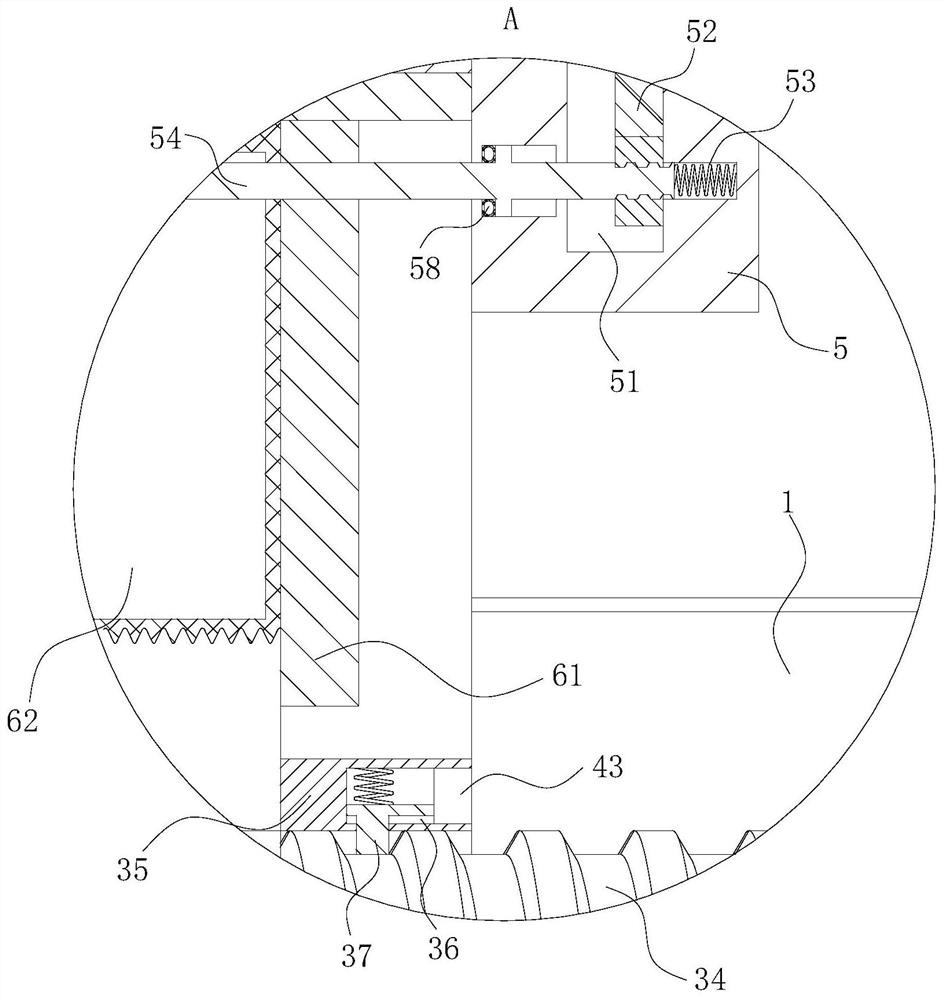
[0028] As an embodiment of the present invention, both sides of the cutting groove 51 are fixedly connected with a scraper 56; the scraper 56 is made of elastic metal sheet material; the scraper 56 and the end of the cutting groove 51 away from the hinge point It is elastically connected by a spring; the scraper 56 is fixedly connected with an expansion bag 57 on the side close to the inner wall of the cutting groove 51; The extruding capsule 58 and the expansion capsule 57 are designed to be connected; during work, when the push rod 54 moves to the inside of the first channel 53, the shape of the extrusion capsule 58 becomes larger, and then the extrusion capsule 58 forms a negative pressure, so that the expansion capsule 57 shrinks, and then the scraper 56 is close to the direction of the side wall of the cutting groove 51, so that the cutting of the cutting knife 52 by the baffle will not be hindered, and when the push rod 54 rebounds and resets, the squeeze bag 58 will diss...


PUM


Abstract

The invention belongs to the technical field of rubber manufacturing, and particularly relates to a rubber preforming device. The rubber preforming device comprises a bottom plate, a material cylinder and a cutting ring; a supporting frame is fixedly connected to the upper portion of the bottom plate; the side, away from the bottom plate, of the supporting frame is arc-shaped, and fixedly connected with the material cylinder; the material cylinder is of a cylindrical cavity type structure; a hopper is fixedly connected to the side, away from the supporting frame, of the material cylinder; the hopper communicates with the inner cavity of the material cylinder; one end, close to the hopper, of the material cylinder is fixedly connected with a power box; and the power box is designed in a disk shape. According to the rubber preforming device provided by the invention, by arranging an extension pipe, a supporting pipe and a transmission rod, the transmission rod is driven to rotate through rotation of a motor, thus the extension pipe is enabled to move at a constant speed through meshing between a connecting ring and a threaded groove in the transmission rod, and then extruded rubber strips are cooled for a period of time by virtue of support of the supporting pipe and the extension pipe; and in this way the rubber strips are primarily hardened and can be conveniently cut by the cutting ring.

Description

technical field [0001] The invention belongs to the technical field of rubber manufacturing, in particular to a rubber preforming device. Background technique [0002] In the rubber preforming machine in the prior art, when the rubber is preformed, a hydraulic device is usually used to extrude the high-temperature rubber into strips, and cut it into a specified size by a cutter, which is convenient for subsequent vulcanization and molding. However, due to the high temperature and soft texture of the rubber itself during the extrusion process, the rubber itself is easy to adhere to the cutter when cutting. At the same time, due to its soft texture, the cut surface will There is a certain deformation, which leads to a certain difference in the weight of the cut rubber block. At the same time, most of the cutting knives in the prior art need to be driven by a cutting motor to cut the rubber strip through high-speed rotation. The high-speed rotating cutter needs to be equipped w...

Claims


Application Information

Patent Timeline
Patent Type & Authority Applications(China)
IPC IPC(8): B29C48/25B26D1/12B26D7/08B29C48/885B29B11/10
CPCB29B11/10B29C48/25B26D1/12B29C48/885B26D7/08
Inventor 汤啸杨君平汤克红范淑贞
Owner ZHEJIANG TIANTAI XIANGHE IND CO LTD
Why Eureka
Try Eureka