A tire packaging machine

A packaging machine and tire technology, applied in the engineering field, can solve the problems of single function and low efficiency, and achieve the effect of convenient collection and transportation

Active Publication Date: 2021-06-18
SHANDONG LINGLONG TIRE
View PDF15 Cites 3 Cited by
  • Summary
  • Abstract
  • Description
  • Claims
  • Application Information

AI Technical Summary

Problems solved by technology

[0002] Tire packaging is a common construction machinery, but the general tire packaging is manually operated, which is inefficient and has a single function

Method used


Image

  • A tire packaging machine
  • A tire packaging machine
  • A tire packaging machine

Examples


specific Embodiment approach 1

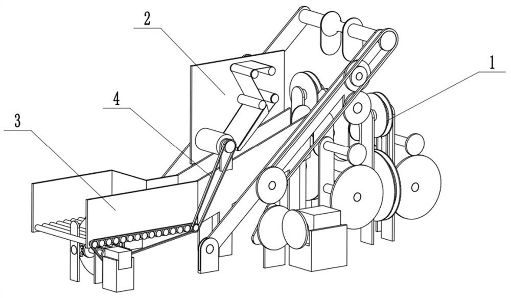
[0027] Bonded below Figure 1-11 In the present embodiment, a tire packaging machine includes a tire wrap device 1, a labeling device 2, a transfer device 3, a belt one 4, and the labeling device 2 is connected to the transfer device 3, and the labeling device 2 and the belt one. 4 is connected, the transfer device 3 is connected to the belt one 4.

specific Embodiment approach 2

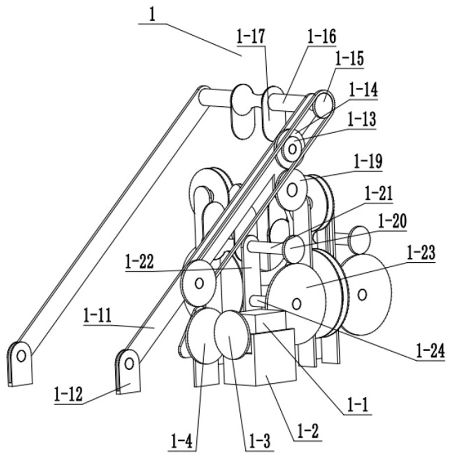
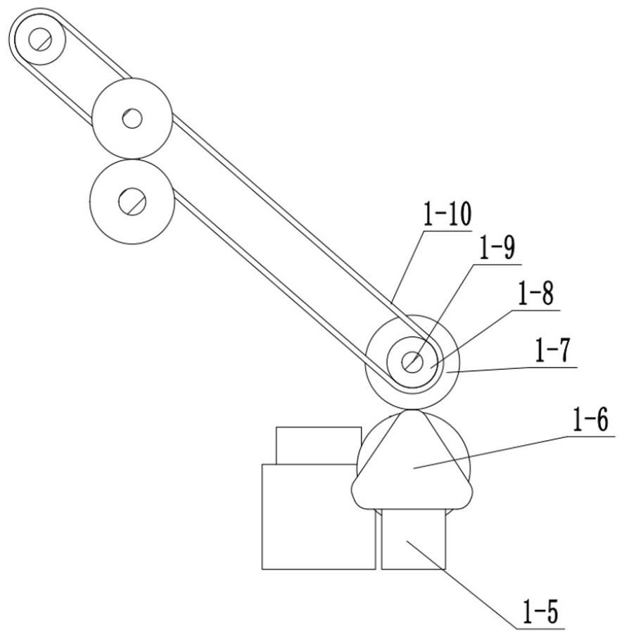
[0029] Bonded below Figure 1-11In the present embodiment, the present embodiment will further explain the embodiment, including a motor 1-1, a motor base 1-2, a runner 1-3, a runner 2-4, a bracket 1-5, a shaped wheel 1-6, runner three 1-7, small wheel three 1-8, small cylinder 1-9, belt 2 1-10, long arm 1-11, pedici 1-12, small Wheel four 1-13, runner four 1-14, runner five 1-15, outer tube one 1-16, fixed plate 1-17, upper fixed wheel 1-18, turn ram six 1-19, runner Seven 1-20, connecting column 1-21, stent three 1-23, connecting column 2 1-24, inner tube 1-25, lower fixed wheel 1-26, fixed plate 2 1-27, outer tube two 1-29, runner nine 1-30, connecting column 10 1-31, inner tube three 1-32, bracket 4 1-33, outer tube three 1- 34, fixed plate three 1-35, lower fixed wheel two 1-36, belt three 1-37, belt four 1-39, belt five 1-40, bracket six 1-41, tape volume 1 -42, functional ring 1-43, circle slot 1-44, small cylindrical 2 1-45, runner eleven 1-46, runner 12 1-47, runner thirte...

specific Embodiment approach 3

[0032] Bonded below Figure 1-11 In this embodiment, the present embodiment will further explain the embodiment, and the labeling device 2 includes a slide 2-1, a bracket 10-2, an output column 2-3, a fixed column 2-4, a fixed column 2-5, back to the roll 2-6, function block 2-7, trademark post 2-8, back plate 2-9, press wheel 2-10, bracket 11 2-11, runner twenty 2- 12, twenty-one 2-13, runner twenty two 2-14, belt 10 2-15, four brackets 10 2-2 are fixed with slide 2-1 fixed connection, output column 2-3, fixed Column 2-4, fixed column 2-5, return column 2-6 Return to the back plate 2-9, function block 2-7 fixed connection with the back plate 2-9, output column 2-3, fixed Pillar 2-4, fixed column 2-5, back roll column 2-6, function block 2-7 is connected to trademark 2-8, and the backplane 2-9 is rotated with the pressure sanner 2-10, Slide 2-1 is fixed to the back plate 2-9, the bracket 11 2-11 is fixedly connected to the slide 2-1, and the press wheel 2-10 is fixedly connected to...


PUM


Abstract

The invention relates to an engineering field, more specifically a tire packaging machine, which meets the actual needs by changing the speed of wrapping tires; through the reciprocating rotation of three functional half-wheels, the tires are laid flat and forwarded to facilitate collection Transportation, changing the position of motor one in the motor base motor base, and then changing the speed of runner two, changing the speed of the opposite wheel, and then changing the speed of lifting and falling of the long arm, and also changing the speed of runner three , changing the rotation speed of belt 2, changing the rotation speed of runner 6, and then changing the rotation speed of runner 7, thus indirectly changing the speed of wrapping tires, and then changing the packaging speed to meet actual needs; when tires and functional brackets When the contact stops, the half gear meshes with the fifth gear and the sixth gear respectively, causing the connecting column 11 to reciprocate left and right, and then drives the three functional half wheels to reciprocate left and right, and then the tire can be laid flat and forwarded for easy collection and transportation .

Description

Technical field [0001] The present invention relates to an engineering field, more specifically a tire packing machine. Background technique [0002] Tire packaging is a common construction machine, but a general tire packaging manual operation, low efficiency, and a single function. Inventive content [0003] It is an object of the present invention to provide a tire packaging machine that can cooperate with the actual demand by changing the speed of the package tire; can be reciprocated by three functional half wheels, and the tire is transferred forward to the collection. [0004] The object of the present invention is achieved by the following technical solutions: [0005] A tire packaging machine includes a tire package device, a labeling device, a transfer device, a belt, and the labeling device is connected to the conveying device, and the labeling device is connected to the belt, and the transfer device is connected to the belt. [0006] As a further optimization of the ...

Claims


Application Information

Patent Timeline
Patent Type & Authority Patents(China)
IPC IPC(8): B65B11/04B65B11/06B65B61/26B65C9/30B65C9/36
Inventor 王锋孙松涛李彦果徐晶孙冰冰马玉静
Owner SHANDONG LINGLONG TIRE
Why Eureka
Try Eureka