
Winding device for cable production

A winding device and cable technology, which is applied in the directions of transportation and packaging, delivery of filamentous materials, thin material processing, etc., can solve the problems of inconvenient removal of cables, poor use effect, loose cables, etc., and achieve better use effect Good, auxiliary cable movement, to avoid the effect of wear

Inactive Publication Date: 2021-04-16
湖南鑫亿电缆有限公司
View PDF0 Cites 5 Cited by
  • Summary
  • Abstract
  • Description
  • Claims
  • Application Information

AI Technical Summary

Problems solved by technology

[0003] At present, during the production process of the cable, a winding device is needed to wind the produced cable, but the existing winding device still has certain deficiencies. During use, the cable wound on the winding roller It is inconvenient to remove, and due to the lack of a certain tension of the cable during the winding process, the cable collected on the winding roller is relatively loose and the use effect is poor. Therefore, it is urgent to design a winding device for cable production to solve the above problems

Method used


Image

  • Winding device for cable production
  • Winding device for cable production
  • Winding device for cable production

Examples


Embodiment 1

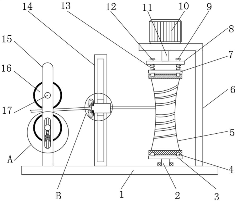
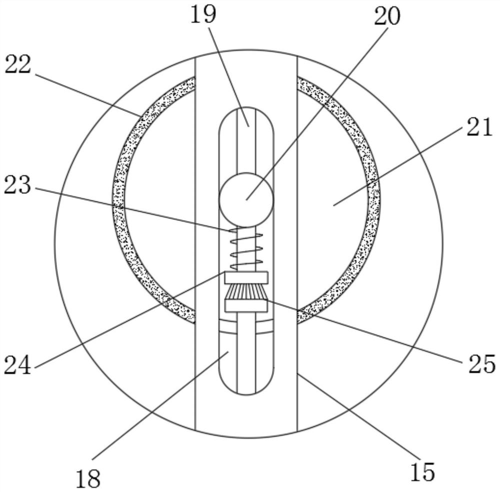
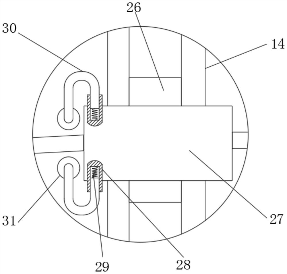
[0029] refer to Figure 1-4 , a winding device for cable production, comprising a bottom plate 1 and a winding roller 5, a mounting frame 6 is fixedly connected to the top outer wall of the bottom plate 1, and a motor 10 is arranged on the top outer wall of the mounting frame 6, and one end of the output shaft of the motor 10 is set There is a rotating shaft 11, and the bottom end of the rotating shaft 11 is provided with a turntable 8, and the top outer wall of the turntable 8 is provided with equidistant circularly distributed through holes, and the inner wall of the through hole is slidingly provided with a limit pin 12, and the top of the limit pin 12 is set There is a stopper 9, and the bottom end of the limit pin 12 is provided with an upper splint 7, the outer wall of the limit pin 12 is sleeved with a first spring 13, the top outer wall of the bottom plate 1 is provided with a movable shaft 2 through bearing rotation, and the movable shaft 2 is provided with a lower cl...

Embodiment 2

[0038] refer to Figure 5 , a winding device for cable production. Compared with Embodiment 1, this embodiment also includes universal wheels 32 at the four corners of the bottom outer wall of the bottom plate 1 .

[0039] Working principle: when in use, the universal wheels 32 located at the bottom of the bottom plate 1 make the device easy to move and more flexible to use.


PUM


Abstract

The invention discloses a winding device for cable production. The winding device for cable production comprises a bottom plate and a winding roller; a mounting frame is fixedly connected to the outer wall of the top of the bottom plate, a motor is arranged on the outer wall of the top of the mounting frame, a rotating shaft is arranged at one end of an output shaft of the motor, and a rotating disc is arranged at the bottom end of the rotating shaft; through holes which are annularly distributed at equal intervals are formed in the outer wall of the top of the rotating disc, limiting pins are slidably arranged on the inner walls of the through holes, stop blocks are arranged at the top ends of the limiting pins, an upper clamping plate is arranged at the bottom ends of the limiting pins, the outer walls of the limiting pins are sleeved with first springs, a movable shaft is rotatably arranged on the outer wall of the top of the bottom plate through a bearing, and a lower clamping plate is arranged at the top end of the movable shaft. By means of the winding device, the winding roller can be easily taken down, replacement with a new winding roller can be conveniently carried out, use is quite convenient, a cable can be evenly wound around the winding roller, abrasion caused by contact between the cable and the inner wall of a cable guide cylinder is effectively avoided, and the use effect is better.

Description

technical field [0001] The invention relates to the technical field of cable production, in particular to a winding device for cable production. Background technique [0002] The cable is usually a rope-like cable made of several or several groups of wires twisted together. Each group of wires is insulated from each other and is often twisted around a center. The entire outside is covered with a highly insulating covering. The cable has The characteristics of internal electrification and external insulation, cables are roughly divided into power cables, control cables, compensation cables, shielded cables, high temperature cables, computer cables, signal cables, coaxial cables, fire-resistant cables, marine cables, mine cables and aluminum alloy cables , mainly used to connect circuits or electrical appliances. [0003] At present, during the production process of the cable, a winding device is needed to wind the produced cable, but the existing winding device still has cer...

Claims


Application Information

Patent Timeline
Patent Type & Authority Applications(China)
IPC IPC(8): B65H54/54B65H54/553B65H67/04B65H54/28B65H57/14B65H59/22
Inventor 贺群喜陈日鑫
Owner 湖南鑫亿电缆有限公司
Learn More