
Printing and dyeing equipment with wastewater separation function

A technology for printing and dyeing equipment and wastewater, which is applied in the direction of textile material equipment configuration, filtration separation, separation methods, etc., to achieve the effects of sufficient separation of wastewater, easy rinsing, and improved utilization

Inactive Publication Date: 2021-04-16
厦门夏曦儿纺织机械有限公司
View PDF0 Cites 0 Cited by
  • Summary
  • Abstract
  • Description
  • Claims
  • Application Information

AI Technical Summary

Problems solved by technology

[0002] In modern printing and dyeing textile enterprises, the textiles printed and dyed by the printing and dyeing device contain a large amount of water, and the water contains a large amount of various chemical raw materials such as dyeing pigments and dyeing aids. Therefore, it is necessary to use dehydration equipment to remove the printing and dyeing wastewater contained in the textiles. Come out, the traditional dehydration method simply dehydrates the bleached and dyed textiles, but the impurities, sludge and other dirt inside the bleached and dyed textiles are not removed

Method used


Image

  • Printing and dyeing equipment with wastewater separation function
  • Printing and dyeing equipment with wastewater separation function
  • Printing and dyeing equipment with wastewater separation function

Examples


Embodiment Construction

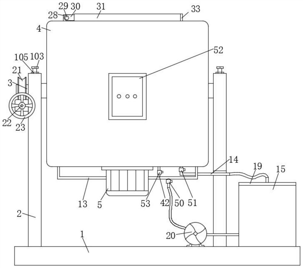
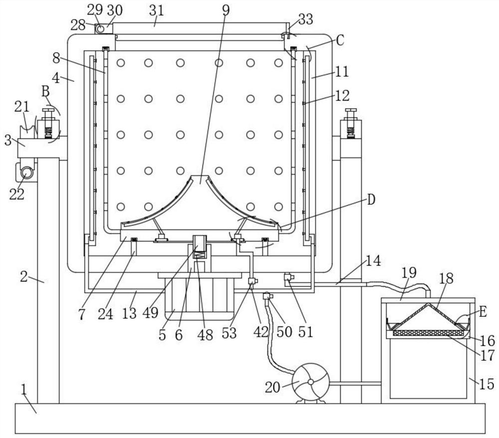
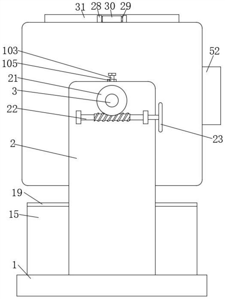
[0028] The following will clearly and completely describe the technical solutions in the embodiments of the present invention with reference to the accompanying drawings in the embodiments of the present invention. Obviously, the described embodiments are only some, not all, embodiments of the present invention.

[0029] refer to Figure 1-9 , a kind of printing and dyeing equipment with waste water separation, including a base 1, a support plate 2 is symmetrically arranged on the left side of the upper surface of the base 1, and a first rotating shaft 3 is arranged on the opposite surface of the two supporting plates 2, and the first rotating shaft 3 One end runs through the outer side of the support plate 2 and is provided with a worm wheel 21, and one side of the support plate 2 is rotated to be provided with a worm 22 matched with the worm wheel 21. The worm 22 rotates, and at the same time, the first rotating shaft 3 rotates through the meshing transmission between the wo...


PUM


Abstract

The invention relates to the technical field of printing and dyeing wastewater treatment, in particular to printing and dyeing equipment with a wastewater separation function. The printing and dyeing equipment comprises a base, wherein first rotating shafts are rotationally arranged on opposite surfaces of two support plates, mounting holes are formed in the upper parts of the two support plates, fixing mechanisms matched with the first rotating shafts are arranged in the mounting holes, a cleaning cylinder is connected between the two first rotating shafts, a servo motor is arranged at the lower end of the cleaning cylinder, a main shaft of the servo motor penetrates through the outer side of the cleaning cylinder and is sleeved with a transmission shaft, a rotary disc is arranged at the end, away from the servo motor, of the transmission shaft, the outer side of the rotary disc is sleeved with a dewatering barrel, a stirring fan is arranged at the upper part of the rotary disc, mounting plates are symmetrically arranged on the inner side of the cleaning cylinder, first water spraying connectors are evenly arranged on the side, away from the cleaning cylinder, of each mounting plate, a water inlet pipe in communication with the mounting plates is arranged on the lower part of the cleaning barrel, and a first electromagnetic valve is arranged on the water inlet pipe. According to the printing and dyeing equipment, impurities and sludge mixed in printed and dyed textiles can be rinsed away, and meanwhile, waste water in the textiles can be separated more sufficiently.

Description

technical field [0001] The invention relates to the technical field of printing and dyeing wastewater treatment, in particular to a printing and dyeing equipment with wastewater detachment. Background technique [0002] In modern printing and dyeing textile enterprises, the textiles printed and dyed by the printing and dyeing device contain a large amount of water, and the water contains a large amount of various chemical raw materials such as dyeing pigments and dyeing aids. Therefore, it is necessary to use dehydration equipment to remove the printing and dyeing wastewater contained in the textiles. Come out, the traditional dehydration method simply dehydrates the bleached and dyed textiles, but the impurities, sludge and other dirt inside the bleached and dyed textiles are not removed. Contents of the invention [0003] The purpose of the present invention is to solve the shortcomings in the prior art, and propose a printing and dyeing equipment with waste water separa...

Claims


Application Information

Patent Timeline
Patent Type & Authority Applications(China)
IPC IPC(8): D06B3/10D06B23/20D06B15/10B01D36/02
Inventor 王芳
Owner 厦门夏曦儿纺织机械有限公司
Learn More