Heat energy slow release and compensation structure of energy-saving heat storage electric heater

A technology of compensation structure and electric heater, which is applied in the direction of heat storage equipment, indirect heat exchanger, heat exchanger type, etc., can solve the problem that the heat release battery life is difficult to achieve the best match, so as to prolong the heating time and reduce the heat loss. The effect of human intervention

Inactive Publication Date: 2021-04-16
ANHUI ANZE ELECTRIC
View PDF17 Cites 0 Cited by
  • Summary
  • Abstract
  • Description
  • Claims
  • Application Information

AI Technical Summary

Problems solved by technology

[0004] There are still deficiencies in traditional energy-saving heat storage appliances: traditional energy-saving heat storage appliances mainly control the strength of convection to control the heat release time and adjust the indoor temperature.
As a result, it is difficult to achieve the best match between the exothermic endurance time and the constant room temperature

Method used


Image

  • Heat energy slow release and compensation structure of energy-saving heat storage electric heater
  • Heat energy slow release and compensation structure of energy-saving heat storage electric heater
  • Heat energy slow release and compensation structure of energy-saving heat storage electric heater

Examples


Embodiment Construction

[0023] The following will clearly and completely describe the technical solutions in the embodiments of the present invention with reference to the accompanying drawings in the embodiments of the present invention. Obviously, the described embodiments are only some, not all, embodiments of the present invention. Based on the embodiments of the present invention, all other embodiments obtained by persons of ordinary skill in the art without creative efforts fall within the protection scope of the present invention.

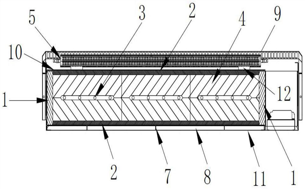
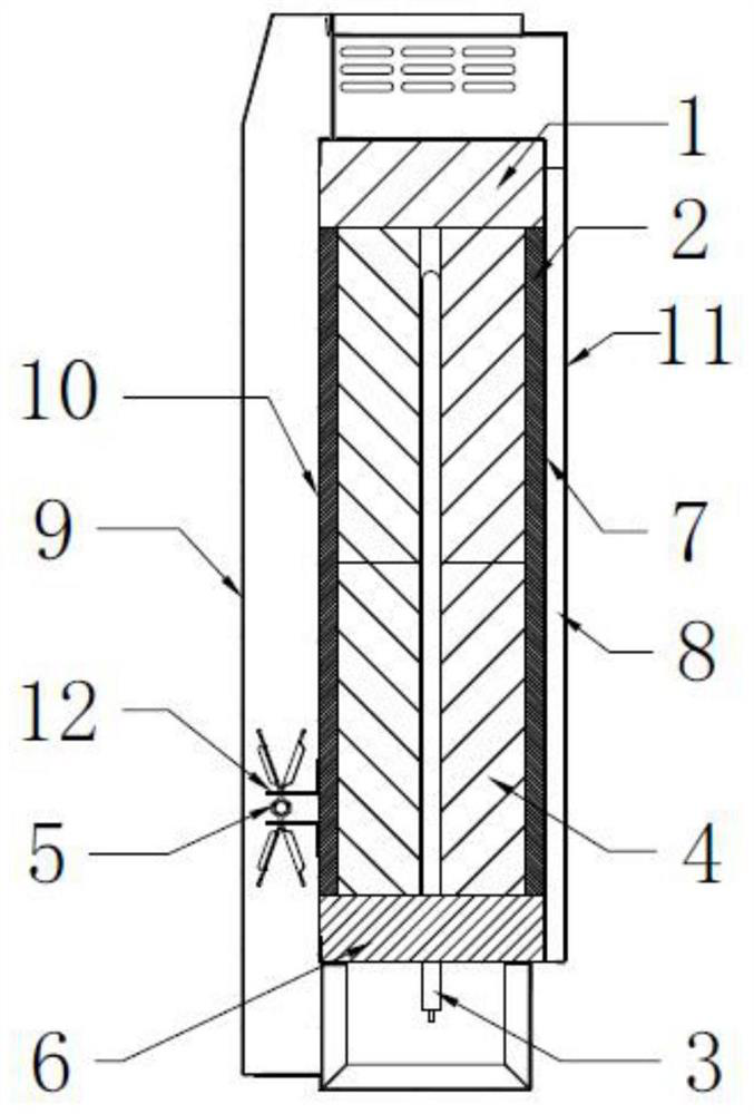
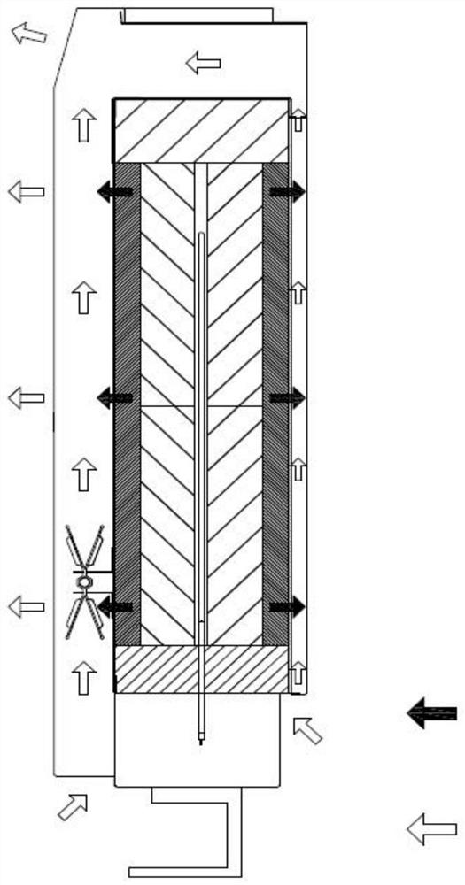
[0024] see Figure 1-3 , the present invention provides a technical solution: a heat energy slow release and heat energy compensation structure of an energy-saving heat storage electric heater, including an inner tank 11, a back partition 7 is placed horizontally and vertically on the inner side of the inner tank 11, the back partition 7 and the inner An inner ventilation channel 8 is formed between the inner tanks 11, and air isolation is formed on the back of the...


PUM


Abstract

The invention discloses a heat energy slow release and heat energy compensation structure of the energy-saving heat storage electric heater in the technical fields of energy-saving heat storage electric heaters. The structure comprises an inner container, a back partition plate is horizontally and vertically placed on the inner side of the inner container, an inner ventilation channel is formed between the back partition plate and the inner container, vermiculite bricks are arranged at the lower end of the interior of the inner container, heat preservation cotton is laid at the top end, the left side and the right side of the inner container, a heat insulation plate is laid on the back partition plate, heat storage bricks are arranged on the heat insulation plate, heating pipes are embedded in the middles of the heat storage bricks, the lower end wiring ends of the heating pipes penetrate through and extend out of the vermiculite bricks, heat storage bricks are arranged above the heating pipes, a heat insulation plate is arranged at the upper ends of the heat storage bricks in the upper portion, a front panel is arranged on the inner container, a support is installed on the lower portion of the outer portion of the front panel, and a fin heating pipe is installed on the support. The heat energy slow release and heat energy compensation structure takes heat storage as a main part and auxiliary heat as an auxiliary part, so that the problems of more loss of heat stored in the heat storage brick layer through openings and larger heat energy loss are solved, and the allowable heating time is greatly prolonged.

Description

technical field [0001] The invention relates to the technical field of energy-saving thermal storage electric heaters, in particular to a heat energy slow release and compensation structure of an energy-saving thermal storage electric heater. Background technique [0002] With the progress of society and the development of technology, heat storage electric heaters with heat storage bricks are more and more popular among users. They can store part of the heat for use during power outages or peak power consumption, and have a certain energy-saving effect. . [0003] Energy-saving thermal storage electric heaters mainly rely on the use of off-peak electricity at night to convert electrical energy into heat energy and store it, and release the stored heat energy during peak electricity hours. The energy-saving heat storage electric heater releases the heat energy mainly through heat convection, heat radiation and heat conduction; among them, heat convection is the most importan...

Claims


Application Information

Patent Timeline
IPC IPC(8): F24D13/02F28D20/00
CPCY02E60/14
Inventor 熊静王继勇葛薇薇
Owner ANHUI ANZE ELECTRIC
Why Eureka
Try Eureka