
Air supply device

A technology of air supply device and tuyere, which is applied in the field of air conditioning equipment, can solve the problems that the air volume of the return air cannot be changed in real time, increase the energy consumption of the overall system, and reduce the utilization rate of the return air, etc., to achieve compact structure, increase induction rate, and improve energy saving The effect of reducing the effect

Pending Publication Date: 2021-04-16
XI'AN UNIVERSITY OF ARCHITECTURE AND TECHNOLOGY
View PDF0 Cites 0 Cited by
  • Summary
  • Abstract
  • Description
  • Claims
  • Application Information

AI Technical Summary

Problems solved by technology

[0004] Aiming at the deficiencies in the prior art, the purpose of the present invention is to provide an air supply device, which solves the problem that the air supply device in the prior art needs to add a static pressure box when dealing with fresh air and indoor return air, and the size of the static pressure box is generally Larger, it is inconvenient to install in office buildings. On the other hand, the air volume of the existing system cannot be changed in real time during the return air process, so the adjustment of the fresh air ratio can only be realized by adjusting the fresh air volume, which increases the energy of the overall system. Consumption, reducing the utilization rate of return air

Method used


Image

  • Air supply device
  • Air supply device
  • Air supply device

Examples


Embodiment 1

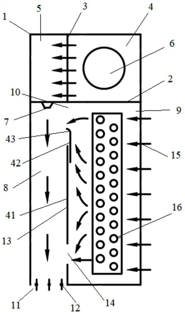
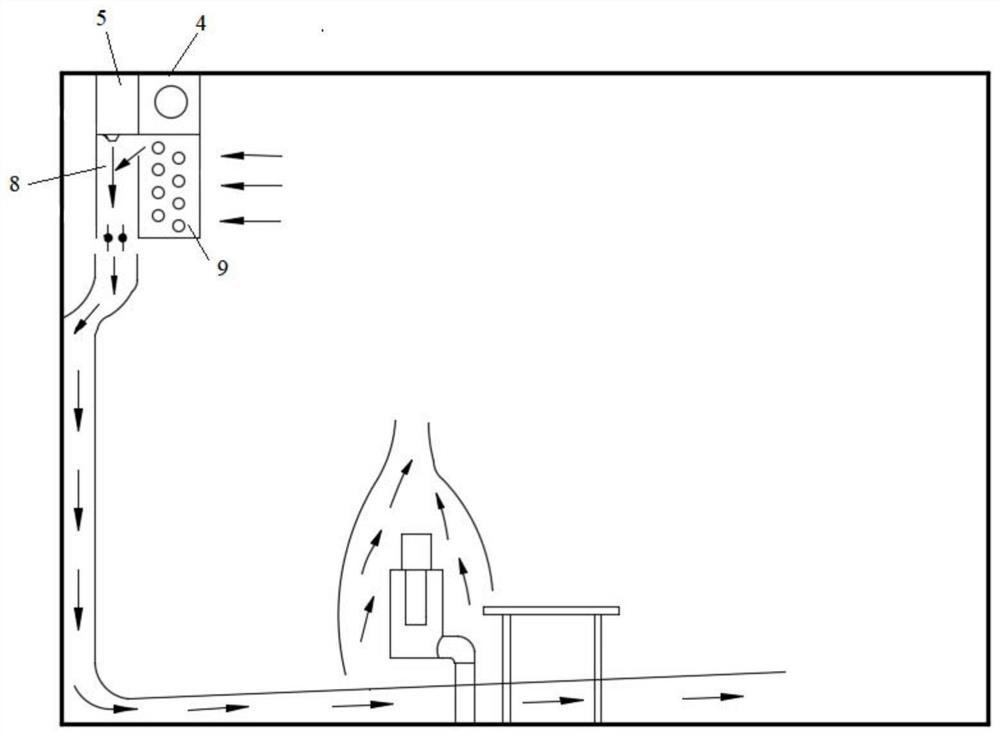
[0037] A wall-attached jet air supply device, such as Figure 1-2 As shown, it includes a casing 1, a cavity is formed in the casing 1, and the air supply device also includes: a partition plate 2, which divides the cavity of the casing 1 into an upper cavity and a lower cavity, and the casing The body 1 is provided with a first air inlet 6 communicating with the upper cavity, and a static pressure device is arranged in the upper cavity; an adjustable baffle 13, and the vertical height of the adjustable baffle 13 is smaller than that of the lower cavity The vertical height of the lower chamber is divided into the induction chamber 8 and the heat exchange chamber 9, the adjustable baffle plate 13 and the top of the lower chamber form the first induction tuyere 10, and a heat exchanger is arranged in the heat exchange chamber 9 16. The shell 1 is provided with a second air inlet 15 communicating with the heat exchange chamber 9, and the side of the induction chamber 8 away from ...

Embodiment 2

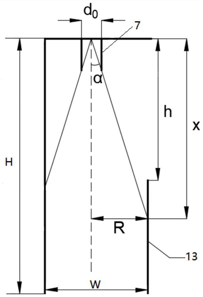
[0063] A design method for adjustable baffles, such as image 3 As shown, the design method includes the following steps:

[0064] S10, set the diameter of the vent as d 0 ; When the jet flow at the vent expands to the jet radius of the adjustable baffle (13) is R, the corresponding jet length is x, and the corresponding jet length is x when the vent jet expands to the adjustable baffle (13);

[0065] S20. Determine the value of the height h of the first induced tuyere (10) according to the corresponding jet length x when the jet flow from the vent expands to the adjustable baffle (13).

[0066] The design method of the adjustable baffle in this embodiment, by controlling the height of the first induced tuyere to be smaller than the corresponding jet length when the jet flow of the vent expands to the adjustable baffle, can ensure that the jet passing through the vent will not enter the heat exchange chamber , to prevent the fresh air from mixing with the indoor air through ...


PUM


Abstract

The invention provides an air supply device. The air supply device comprises a shell, a partition plate, a flow equalizing plate and an the adjustable baffle, wherein a cavity is formed in the shell, the partition plate divides the cavity of the shell into an upper cavity body and a lower cavity body, the flow equalizing plate is vertically arranged in the upper cavity and divides the upper cavity into an air inlet cavity and a static pressure cavity, a first air inlet communicating with the air inlet cavity is formed in the shell, the vertical height of the adjustable baffle is smaller than that of the lower cavity body, the adjustable baffle divides the lower cavity body into an induction cavity and a heat exchange cavity, a first induction air port is formed by the adjustable baffle and the top of the lower cavity body, a heat exchanger is arranged in the heat exchange cavity, a second air inlet communicating with the heat exchange cavity is formed in the shell, and a first air outlet is formed in one side, far away from the upper cavity body, of the induction cavity. According to th eair supply device, the partition plate is provided with a ventilation opening communicating with the static pressure cavity and the induction cavity, indoor return air is prevented from passing through an air outlet and then being conveyed to the first air inlet through an air pipe to enter the air supply device, and energy consumption of the indoor return air in the conveying process is reduced.

Description

technical field [0001] The invention belongs to the field of air conditioners, and in particular relates to an air supply device. Background technique [0002] With the development of science and technology, more and more work can be done indoors. Modern people spend 80% to 90% of their time indoors living and working in the indoor environment. Therefore, the quality of the indoor environment directly affects people's health. To maintain good health, an effective way to improve indoor air quality is to improve indoor air circulation, accelerate the discharge of indoor polluted air, and accelerate the injection of outdoor fresh air. [0003] In the existing air supply device, the indoor return air needs to be discharged from the room through a separate air outlet, enter the air handling unit and mix with the fresh air, and then be sent to the terminal air supply device. In the actual use process, the static pressure box needs to be processed at the same time Fresh air and in...

Claims


Application Information

Patent Timeline
Patent Type & Authority Applications(China)
IPC IPC(8): F24F1/0011F24F1/0035F24F1/0063F24F13/14
CPCF24F1/0007F24F1/01F24F13/12F24F7/06
Inventor 杨斌周斌杨长青高然尹海国李安桂
Owner XI'AN UNIVERSITY OF ARCHITECTURE AND TECHNOLOGY
Learn More