Ward distributed ventilation system and control method

A ventilation system and distributed technology, applied in the field of ward ventilation, can solve the problems of the ventilation system not working normally, taking a long time, and high cost, and achieve the effect of reducing the probability of cross-infection, convenient and fast installation, and quick installation

Active Publication Date: 2021-04-16
CHONGQING BLUEHORIZON ENERGY-SAVING TECH CO LTD
View PDF8 Cites 1 Cited by
  • Summary
  • Abstract
  • Description
  • Claims
  • Application Information

AI Technical Summary

Problems solved by technology

[0004] At present, most of the bathrooms are ventilated by exhaust fans for top row, and the pollutants in the bathroom are mainly ammonia and hydrogen sulfide, among which ammonia is lighter than air, and hydrogen sulfide is heavier than air, which causes the pollutants in the bathroom to be vertically distributed. There will be vertical distribution in the vertical space, and because the toilet is installed in the lower part of the bathroom, there will be more pollutants in the lower part of the bathroom
None of the existing setting methods can fully and effectively exhaust the bathroom
[0005] Some toilets in old buildings do not even have a ventilation system, or the ventilation system is no longer in normal use, and urgently needs renovation. However, the existing renovation methods require major changes to the building, which takes a long time and costs a lot.

Method used


Image

  • Ward distributed ventilation system and control method
  • Ward distributed ventilation system and control method
  • Ward distributed ventilation system and control method

Examples


Embodiment Construction

[0023] Below by embodiment and in conjunction with accompanying drawing, the present invention will be further described:

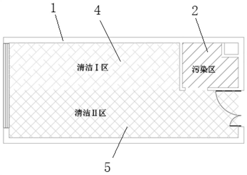
[0024] to combine figure 1 — Figure 5 As shown, a ward distributed ventilation system is equipped with toilet 2 in ward 1. In the ward 1, several sick beds are arranged along the length direction, and the head of all the sick beds are arranged at intervals against the same wall, and the space occupied by all the sick beds together constitutes a clean area 4 . The space from the end of all sickbeds to the opposite wall together constitutes the second cleaning zone 5 .

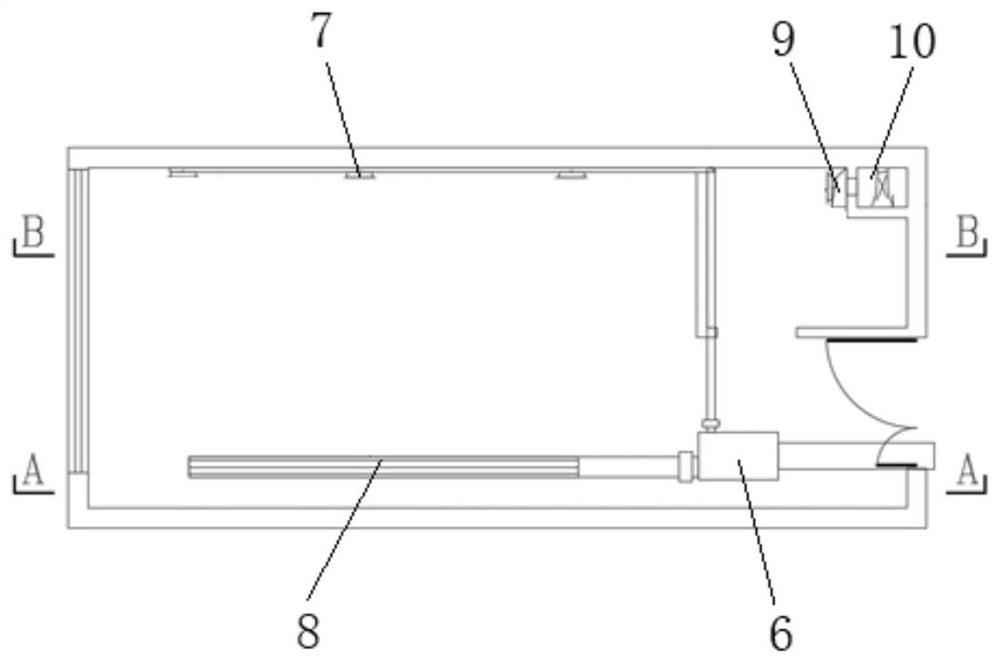
[0025] The distributed ventilation system of the ward includes a distributed air supply system and a distributed exhaust system.

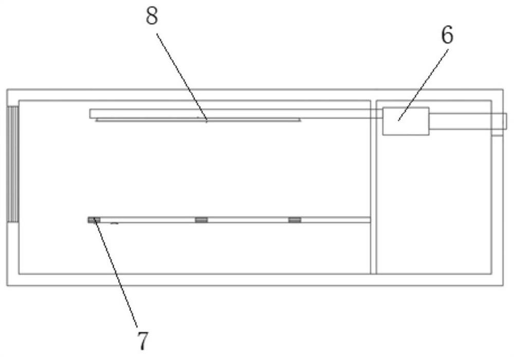
[0026] The distributed air supply system is mainly composed of an air supply power module 6, an air supply pipeline, an air supply outlet 7 at the head of the bed and an air supply outlet 8 at the end of the bed. The bedside air supply outlet 7 is provided ...


PUM


Abstract

The invention discloses a ward distributed ventilation system which comprises a distributed air supply system and a distributed exhaust system, and the distributed air supply system comprises an air supply power module, an air supply pipeline, a bed head air supply opening and a bed tail air supply opening; the distributed exhaust system comprises an exhaust power module and a vertical exhaust pipe, a lower exhaust outlet is formed in the lower portion of the vertical exhaust pipe, an upper exhaust outlet is formed in the middle of the vertical exhaust pipe, an exhaust port is formed in the upper portion of the vertical exhaust pipe, the lower exhaust outlet and the upper exhaust outlet are located in the front face of the vertical exhaust pipe, and the exhaust port is located in the back face of the vertical exhaust pipe. Meanwhile, the invention further discloses a control method of the ward distributed ventilation system. Fresh air can be respectively fed into a patient activity area and a visiting and accompanying personnel activity area, the sanitary fresh air requirements of various personnel are met, airflow is controlled to be not crossed, and the probability of cross infection of hospitals is reduced; and the modular exhaust structure can be rapidly installed and can be rapidly connected into exhaust equipment, installation is convenient and rapid, the cost is low, and meanwhile peculiar smells in a toilet can be comprehensively and effectively exhausted.

Description

technical field [0001] The invention belongs to the technical field of ward ventilation, and in particular relates to a ward distributed ventilation system and a control method. Background technique [0002] The indoor thermal environment adjustment of the hospital is to pursue comfort, and the ventilation system is an important means to ensure the health of indoor personnel. At present, the design and operation of ventilation and air-conditioning systems in general wards mainly focus on the control of temperature and humidity in the wards. The ventilation system is reduced to the auxiliary design of the air-conditioning system. The fresh air and indoor air distribution cannot discharge indoor pollutants well, and cannot guarantee the cleanliness of the breathing area of ​​the personnel in the ward and the air safety in the ward. [0003] For a long time, although people are disgusted by the smell in the bathroom, there is nothing they can do about it. As people's requirem...

Claims


Application Information

Patent Timeline
Patent Type & Authority Applications(China)
IPC IPC(8): F24F7/08F24F11/64F24F11/74F24F11/77F24F11/89F24F13/02F24F110/50F24F120/10E04H3/08
CPCY02B30/70F24F7/08F24F11/64F24F11/74F24F11/89F24F11/77F24F13/02F24F2110/50F24F2120/10E04H3/08
Inventor 郭金成黄雪居发礼侯昌垒丁艳蕊
Owner CHONGQING BLUEHORIZON ENERGY-SAVING TECH CO LTD
Why Eureka
Try Eureka