Compensation pulse generator system

A technology for compensating pulses and generators, applied in the direction of electromechanical devices, electrical components, electric components, etc., can solve the problems of how to arrange the incoming lines of excitation feeders, etc., and achieve the effect of convenient and flexible disassembly and maintenance

Active Publication Date: 2021-04-16
INST OF ELECTRICAL ENG CHINESE ACAD OF SCI
View PDF7 Cites 0 Cited by
  • Summary
  • Abstract
  • Description
  • Claims
  • Application Information

AI Technical Summary

Problems solved by technology

Among these schemes, most of them are motors with special structures, and there is no detailed and feasible scheme for how to arrange the incoming lines of the excitation feeder; the compensating pulse generator usually adopts slotless excitation winding and armature winding, so as to meet the requirements of reducing winding inductance during high-speed rotation, To increase the energy storage density, the commonly used compensating pulse generator is an inner rotor motor, and the excitation winding is located in the middle of the radial direction. Due to the compact structure of the motor, the components need to be closely matched, and the discharge current of the pulse compensating generator is very large , needs perfect insulation protection, therefore, the layout of the excitation feeder, how to connect the excitation winding coil from the outside becomes a difficult problem and an important problem that must be solved

Method used


Image

  • Compensation pulse generator system
  • Compensation pulse generator system
  • Compensation pulse generator system

Examples


Embodiment Construction

[0034] Preferred embodiments of the present invention are described below with reference to the accompanying drawings. Those skilled in the art should understand that these embodiments are only used to explain the technical principle of the present invention, and are not intended to limit the protection scope of the present invention.

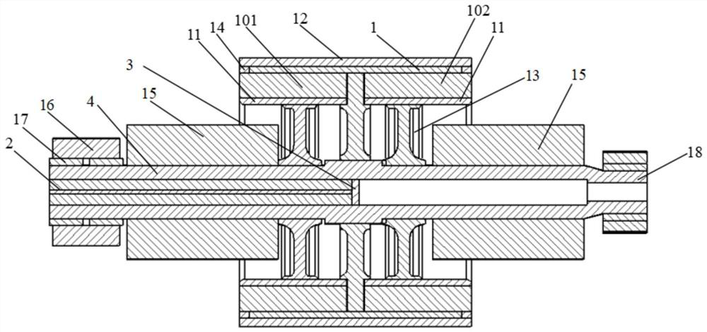
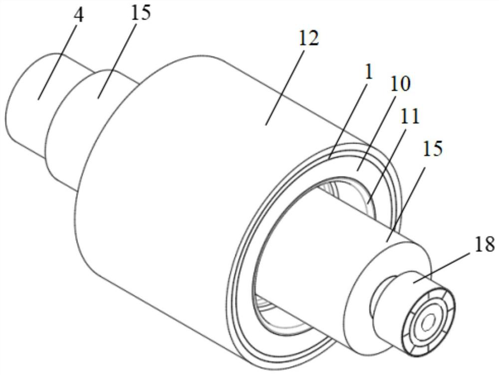
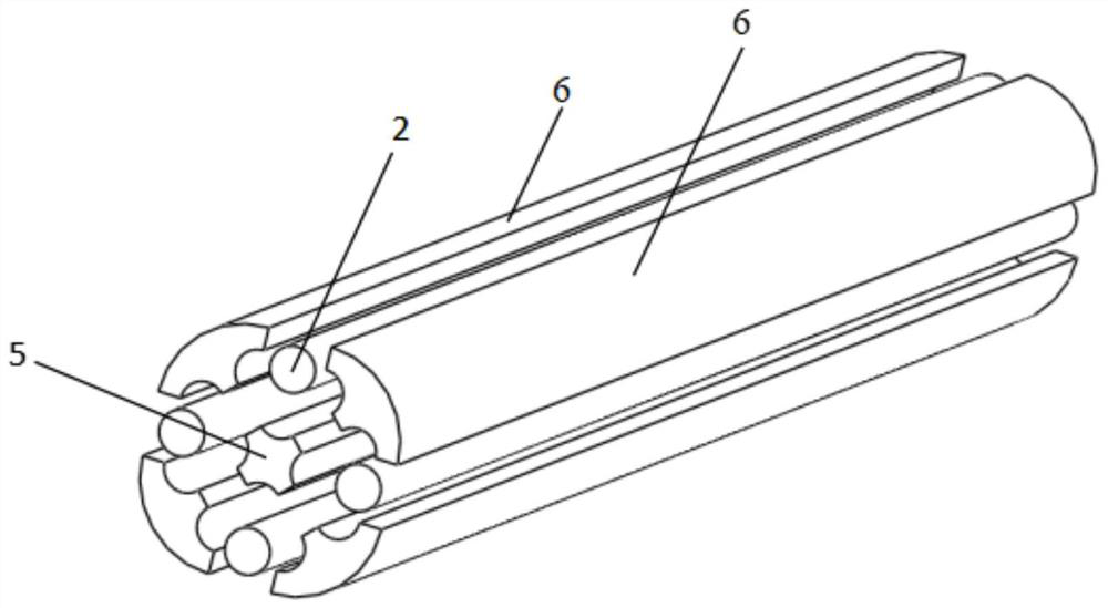
[0035] A compensating pulse generator system, including a stator, a rotor and a casing, wherein the stator includes a stator core and a stator winding, the stator winding is arranged at both ends of the stator core, and the stator core is arranged on the inner wall of the casing, the power generation The machine system also includes a hollow shaft, an excitation winding and an excitation feeder device. The excitation feeder device is used to establish communication between the excitation winding and the outside; the excitation feeder device includes an excitation feeder assembly and an excitation outlet assembly; the excitation feeder assembly in...


PUM


Abstract

The invention belongs to the technical field of motors, aims to solve the problem of how to access an excitation winding into an excitation feeder of a compensation pulse generator, and provides a compensation pulse generator system. The system comprises a stator core, stator windings arranged at two ends of the stator core, a rotor, a casing, a hollow shaft, an excitation winding and an excitation feeder device. The excitation feeder device is used for constructing communication between the excitation winding and the outside. The excitation feeder device comprises an excitation feeder assembly and an excitation outgoing line assembly. The excitation feeder assembly comprises an excitation feeder and an excitation feeder clamping assembly, and the excitation feeder is arranged in the shaft hole of the hollow shaft through the excitation feeder clamping assembly. The excitation outgoing line assembly is arranged outside the hollow shaft and is communicated with the excitation feeder assembly through a claw pole disc assembly. Excitation leads comprise a first group of excitation leads and a second group of excitation leads. The claw pole disc assembly comprises two claw pole discs which are meshed with each other, so that double excitation leads can be led out from the excitation feeder through the two claw pole discs.

Description

technical field [0001] The invention belongs to the technical field of motors, and in particular relates to a compensating pulse generator system. Background technique [0002] The compensating pulse generator is a high-power pulse power supply with inertial energy storage, which provides high-current pulses to the load. It has comprehensive advantages in energy density and power density. At present, it is developing rapidly as a high-power pulse power supply for driving electromagnetic guns with high power. , In addition, in the industrial field, it can also be used for electromagnetic forming, electromagnetic smelting, etc., and has broad application prospects. [0003] Compensated pulse generators also use flywheel energy storage technology. Flywheel energy storage generally refers to the two-way conversion between electric energy and flywheel kinetic energy. It can have the advantages of high power density, long cycle life, rapid response, good energy observability and ...

Claims


Application Information

Patent Timeline
Patent Type & Authority Applications(China)
IPC IPC(8): H02K39/00H02K3/50H02K3/47H02K7/02
CPCY02E60/16
Inventor 陈晨赵慧斌王又珑古蕾张颖温旭辉
Owner INST OF ELECTRICAL ENG CHINESE ACAD OF SCI
Why Eureka
Try Eureka