Water conservancy aquatic plant removing equipment

A technology of aquatic plants and equipment, applied in the direction of cutters, agricultural machinery and implements, applications, etc., can solve problems such as unfavorable aquatic plants

Inactive Publication Date: 2021-04-20
杨福明
View PDF0 Cites 2 Cited by
  • Summary
  • Abstract
  • Description
  • Claims
  • Application Information

AI Technical Summary

Problems solved by technology

[0002] Aquatic weed removal equipment is a common water conservancy machine, but general water conservancy and aquatic weed removal equipment can only cut aquatic plants in one direction, and only pile them up after cutting, and do not use aquatic plants

Method used


Image

  • Water conservancy aquatic plant removing equipment
  • Water conservancy aquatic plant removing equipment
  • Water conservancy aquatic plant removing equipment

Examples


specific Embodiment approach 1

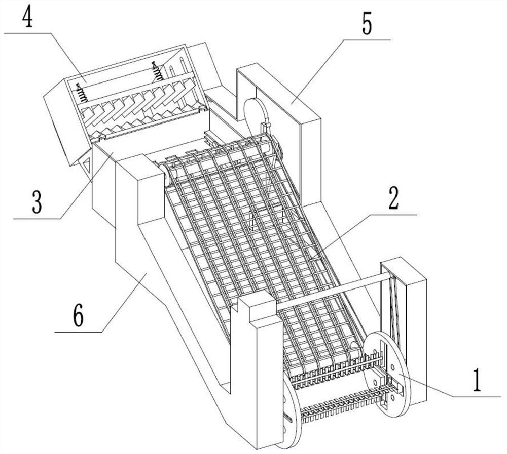
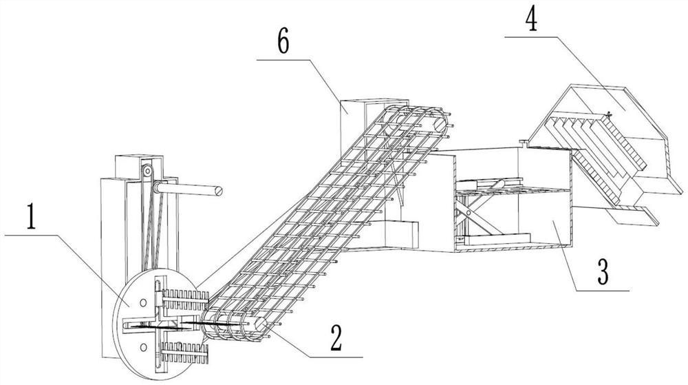
[0039] Combine below Figure 1-20 Describe this embodiment, a kind of water conservancy and water weed removal equipment, comprise mowing device 1, feeding device 2, cleaning device 3, pulverizing device 4, casing weldment A5, casing weldment B6, described mowing device 1 and feeding Device 2 is connected, feeding device 2 is connected with cleaning device 3, cleaning device 3 is connected with crushing device 4, mowing device 1 is connected with cleaning device 3, mowing device 1, feeding device 2, cleaning device 3, crushing The devices 4 are all connected with the casing weldment A5, and the mowing device 1, the feeding device 2, and the cleaning device 3 are all connected with the casing weldment B6.

specific Embodiment approach 2

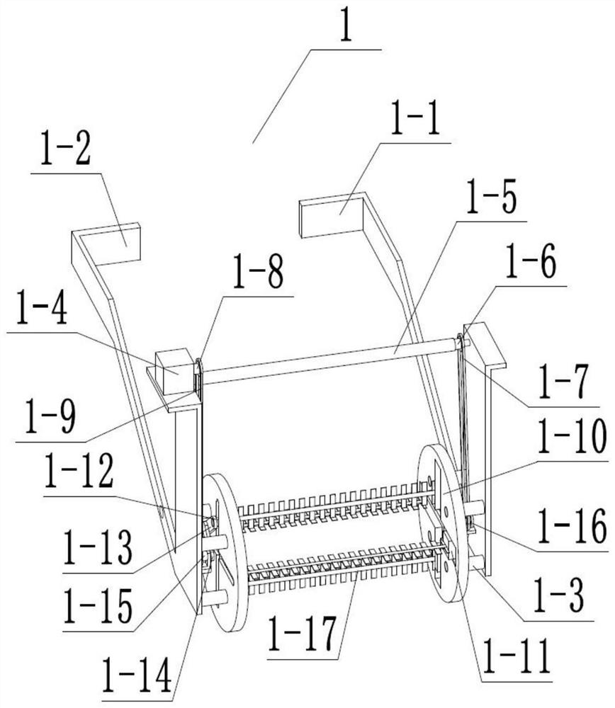
[0041] Combine below Figure 1-20 Describe this embodiment, this embodiment will further describe the first embodiment, the mowing device 1 includes a mowing fixed plate A1-1, a mowing fixed plate B1-2, a mowing fixed shaft 1-3, and a motor 1-4 , motor shaft 1-5, gear A1-6, chain A1-7, gear B1-8, chain B1-9, slider fixed plate 1-10, slider 1-11, slider connecting shaft 1-12, slider Block connecting plate 1-13, rotating plate 1-14, double gear A1-15, double gear B1-16, cutting blade 1-17, mowing fixed shaft 1-3 is welded and connected with mowing fixed plate A1-1, mowing The grass fixed shaft 1-3 is welded and connected with the mowing fixed plate B1-2, the mowing fixed shaft 1-3 is fixedly connected with the slider fixed plate 1-10, and the motor 1-4 is fixedly connected with the mowing fixed plate B1-2, The output shaft of the motor 1-4 is connected in rotation with the gear B1-8, the gear B1-8 is connected in rotation with the chain B1-9, the chain B1-9 is connected in rota...

specific Embodiment approach 3

[0044] Combine below Figure 1-20 Describe this embodiment, this embodiment will further describe the first embodiment, the feeding device 2 includes a transmission chain 2-1, a transmission gear 2-2, a rotating shaft A2-3, a rotating shaft B2-4, a chain welding shaft 2-5, Double gear C2-6, chain C2-7, transmission chain 2-1 is connected in rotation with transmission gear 2-2, transmission gear 2-2 is connected with rotation shaft A2-3, rotation shaft B2-4 respectively, transmission chain 2-1 is connected with rotation The chain welding shaft 2-5 is welded and connected, the double gear C2-6 is rotatably connected with the rotating shaft B2-4, the chain C2-7 is rotatably connected with the double gear C2-6, and the chain C2-7 is rotatably connected with the double gear B1-16.

[0045] The double gear B1-16 rotates to drive the chain C2-7, which drives the double gear C2-6 to rotate, so that the rotating shaft B2-4 drives the transmission gear 2-2 to rotate, and the transmissio...


PUM


Abstract

The invention relates to the field of water conservancy, in particular to aquatic plant removing equipment. Aquatic plants can be cut off in four directions, and cleaned, filtered and dried and then smashed into particles, animal feed can be prepared in the later period, and full utilization is achieved. The equipment comprises a mowing device, a feeding device, a cleaning device, a smashing device, a housing weldment A, a housing weldment B. A motor is started to drive a gear B, a double-gear A is made to rotate, a motor rotating shaft is made to rotate, a rotating plate is made to rotate, a sliding block slides in a sliding groove of a sliding block fixing disc, and a cutting blade is driven to slide up and down and left and right, so that the effect of cutting off the aquatic plants in the four directions is achieved; a double-gear C drives a double-gear D to rotate and drives a cam to rotate, so that a cleaning screen moves up and down; an overturning stop block blocks the cleaning screen to enable the other side of the cleaning screen to rise, the aquatic plants slide down, the gear C rotates, a connecting plate B rotates, and a cutter connecting shaft moves along a notch of a crushing frame; and when a smashing cutter A moves forwards and is tangent to a smashing cutter B, the function of cutting the aquatic plants is achieved.

Description

technical field [0001] The invention relates to the field of water conservancy, in particular to a device for removing aquatic plants. Background technique [0002] Aquatic weed removal equipment is a common water conservancy machine, but general water conservancy and aquatic weed removal equipment can only cut aquatic plants in one direction, and only pile them up after cutting, and do not use aquatic plants. Contents of the invention [0003] The purpose of the present invention is to provide a water conservancy and aquatic weed removal equipment, which can realize the cutting of aquatic plants in four directions, and the aquatic plants are cleaned, filtered and dried, and then crushed into granules, which can be made into animal feed in the later stage to achieve full utilization. [0004] The purpose of the present invention is achieved through the following technical solutions: [0005] A water conservancy and aquatic weed removal equipment, comprising a grass mowing...

Claims


Application Information

Patent Timeline
Patent Type & Authority Applications(China)
IPC IPC(8): A01D44/00A01D43/00A01D43/08
Inventor 杨福明
Owner 杨福明
Why Eureka
Try Eureka