
Automatic cement floor laying device

An automatic laying and cement technology, which is applied in the field of building pouring, can solve the problems of difficult operation, uneven position thickness, time-consuming and wasteful energy, etc., and achieve the effect of difficult operation

Inactive Publication Date: 2021-04-20
漳州盛之昌贸易有限公司
View PDF0 Cites 0 Cited by
  • Summary
  • Abstract
  • Description
  • Claims
  • Application Information

AI Technical Summary

Problems solved by technology

[0002] During building construction, the cement floor work is one of the necessary work. This work needs to pour the cement to the corresponding position first, and then the workers drag it to the vibrator to make the cement fully mixed to avoid the generation of holes. Finally, it is smoothed by manual scraping. The surface construction is completed, but when the workers are operating, the cement pouring position is single, resulting in uneven thickness of the cement pouring position, and the subsequent shaking time is too long, and the vibrator needs to be continuously dragged during pouring, and all pouring positions must be guaranteed to be poured Uniform, resulting in difficult operation, time-consuming and labor-intensive, and after the pouring is completed, a special person needs to be scraped, which makes the work efficiency lower and the labor intensity of the workers is high. In view of the above shortcomings, the present invention improves

Method used


Image

  • Automatic cement floor laying device
  • Automatic cement floor laying device
  • Automatic cement floor laying device

Examples


Embodiment Construction

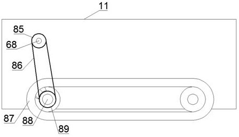
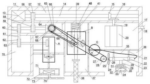
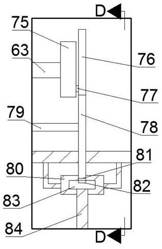
[0019] Combine below Figure 1-6 The present invention is described in detail, wherein, for the convenience of description, the orientations mentioned below are defined as follows: figure 1 The up, down, left, right, front and back directions of the projection relationship itself are the same.

[0020]A cement floor automatic laying equipment described in conjunction with accompanying drawings 1-6 includes a main body 11, a first power chamber 12 is provided in the main body 11, and a first motor 13 is fixed in the first power chamber 12 The first motor 13 is rotatably provided with a first motor shaft 14, the first motor shaft 14 is fixed with a first bevel gear 15, and the first power chamber 12 is rotatably provided with a first A rotating shaft 19, the first rotating shaft 19 is fixed with a second bevel gear 16, the first bevel gear 15 meshes with the second bevel gear 16, the main body 11 is provided with a cement mixing chamber 17, the One end of the first rotating sh...


PUM


Abstract

The invention discloses an automatic cement floor laying device. The automatic cement floor laying device comprises a main body, wherein a power cavity is fixedly formed in the main body; a first motor is fixedly arranged in the power cavity; a first motor shaft is rotatably arranged on the first motor; and an auxiliary power cavity is formed in the main body. The motor drives travelling wheels to travel, so that the device moves freely; a left-right swinging sweeping mechanism controlled by the motor can replace manual operation to sweep dust; and a dust collecting device and a spraying device are arranged in the device, the sweeping mechanism swings in the left-right direction to control the two devices to be opened at an interval, and therefore, dust in air is fully wetted and adhered by water and then is collected by the dust collecting device. The device is simple in structure and convenient to maintain in the later period, can perfectly use machinery to replace manual operation, and is high in practicality, the operation efficiency is improved, and the risk of manual operation is reduced.

Description

technical field [0001] The invention relates to a cement floor automatic laying equipment, and mainly relates to the technical field related to building pouring. Background technique [0002] During building construction, the cement floor work is one of the necessary work. This work needs to pour the cement to the corresponding position first, and then the workers drag it to the vibrator to make the cement fully mixed to avoid the generation of holes. Finally, it is smoothed by manual scraping. The surface construction is completed, but when the workers are operating, the cement pouring position is single, resulting in uneven thickness of the cement pouring position, and the subsequent shaking time is too long, and the vibrator needs to be continuously dragged during pouring, and all pouring positions must be guaranteed to be poured Uniformity makes the operation difficult, time-consuming and labor-intensive, and it needs to be leveled by a special person after the pouring i...

Claims


Application Information

Patent Timeline
Patent Type & Authority Applications(China)
IPC IPC(8): E04F21/24
Inventor 李玉翰
Owner 漳州盛之昌贸易有限公司
Learn More