Automatic control type electric tower column with high wind resistance

A technology of capacity and electric tower, applied in the field of self-control electric tower column, can solve the problems of difficult to achieve support and stability, too late to operate, and the land area is not beautiful enough.

Inactive Publication Date: 2021-04-20
上海维经斯电子科技有限公司
View PDF0 Cites 0 Cited by
  • Summary
  • Abstract
  • Description
  • Claims
  • Application Information

AI Technical Summary

Problems solved by technology

[0002] The electric tower column is a kind of municipal power transmission device, which is commonly used in some areas of urban villages. However, when this type of electric tower column encounters strong winds, due to its high height and insufficient stability at the bottom, it is easy to collapse and cause safety hazards. Accidents and unnecessary losses, and if the auxiliary support frame is used for support and reinforcement, it is too late to operate in case of an emergency. If it is reinforced in normal times, it will not only waste the use of the land area, but also easily lead to long-term support of the support frame. It leads to the embrittlement of materials, so that it is difficult to achieve the effect of supporting and stabilizing in strong winds. The self-controlled electric tower column with high wind resistance described in the present invention can solve the above problems

Method used


Image

  • Automatic control type electric tower column with high wind resistance
  • Automatic control type electric tower column with high wind resistance
  • Automatic control type electric tower column with high wind resistance

Examples


Embodiment Construction

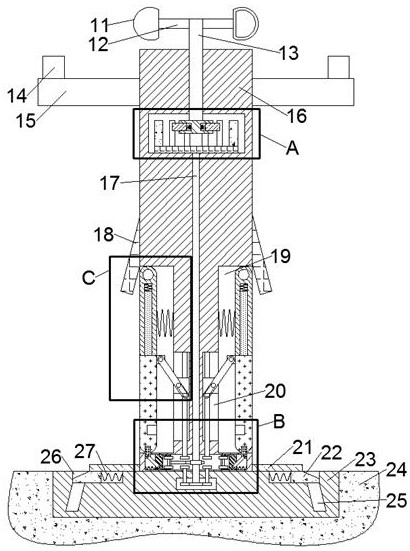
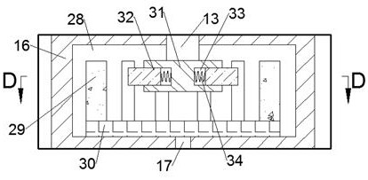
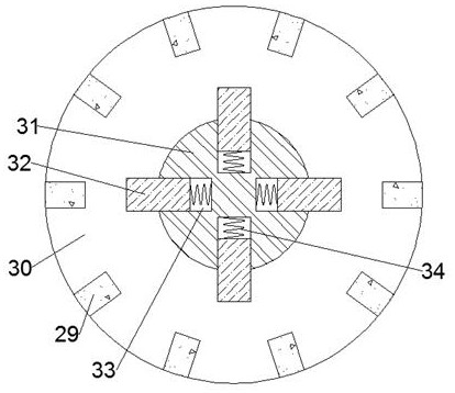
[0016] Combine below Figure 1-5 The present invention is described in detail, wherein, for the convenience of description, the orientations mentioned below are defined as follows: figure 1 The up, down, left, right, front and back directions of the projection relationship itself are the same.

[0017] A self-controlled electric tower column with high wind resistance according to the present invention includes a column body 16, a gravity body 23 is fixed on the bottom surface of the column body 16, and the gravity body 23 is embedded and fixedly installed in the formation 24 Inside, the top surface of the cylinder 16 is rotated with a rotating shaft 13, and the outer circumference of the rotating shaft 13 is fixed with two symmetrical connecting columns 12, and the connecting columns 12 are fixed on the side of the rotating shaft 13 away from There is a windward bucket 11, and a control cavity 28 is opened in the cylinder 16, and the extension part of the lower side of the ro...


PUM


Abstract

The invention discloses a self-control type electric tower column with the high wind resistance. The self-control type electric tower column comprises a column body, wherein a gravity body is fixedly arranged on the bottom surface of the column body, the gravity body is fixedly installed in a stratum in an embedded mode, a rotating shaft is rotatably arranged on the top surface of the column body, two connecting columns which are symmetrical left and right are fixedly arranged on the periphery of the rotating shaft, windward hoppers are fixedly arranged on the side faces, away from the rotating shaft, of the connecting columns, a control cavity is formed in the column body, the extending part of the lower side of the rotating shaft extends into the control cavity, a telescopic rotating disc is fixedly arranged on the bottom face of the rotating shaft, and four telescopic cavities with openings facing the control cavity are formed in the telescopic rotating disc. According to the self-control type electric tower column, an electric tower can automatically control a stable frame plate to be unfolded and connected with the gravity body fixedly embedded under the ground in case of strong wind in external weather, so that when the electric tower column is attacked by fierce wind, the stability of the bottom is stronger, the electric tower column is not easy to collapse, and the safety is effectively improved.

Description

technical field [0001] The invention relates to the related field of electric equipment, in particular to a self-controlled electric tower column with high wind resistance. Background technique [0002] The electric tower column is a kind of municipal power transmission device, which is commonly used in some areas of urban villages. However, when this type of electric tower column encounters strong winds, due to its high height and insufficient stability at the bottom, it is easy to collapse and cause safety hazards. Accidents and unnecessary losses, and if the auxiliary support frame is used for support and reinforcement, it is too late to operate in case of an emergency. If it is reinforced in normal times, it will not only waste the use of the land area, but also easily lead to long-term support of the support frame. This leads to the embrittlement of materials, which makes it difficult to achieve the effect of supporting and stabilizing in strong winds. The self-controll...

Claims


Application Information

Patent Timeline
Patent Type & Authority Applications(China)
IPC IPC(8): E04H12/00E04H12/18E04H12/22E04H12/24F03D9/20F03D9/43F03D3/00F03D3/06F03D15/00
CPCY02B10/30Y02E10/728Y02E10/74
Inventor 聂松芬
Owner 上海维经斯电子科技有限公司
Why Eureka
Try Eureka