
Combined type device and method for measuring drilling depth

A drilling depth, combined technology, applied in drilling equipment and methods, measurement, drill pipe and other directions, can solve problems such as drill pipe sticking, increase work costs, affect labor efficiency, etc., to ensure accuracy and real-time performance , to ensure the effect of accuracy and authenticity

Pending Publication Date: 2021-04-20
深圳市城安物联科技有限公司
View PDF12 Cites 4 Cited by
  • Summary
  • Abstract
  • Description
  • Claims
  • Application Information

AI Technical Summary

Problems solved by technology

[0003] During the use of drill pipes, the drilling depth needs to be measured. The traditional measurement method is to manually count the number of drill pipes drilled. On the one hand, this method increases the workload of technicians, increases work costs, and affects labor efficiency. On the other hand, it is also prone to human errors caused by worker fatigue, and the measurement results are not necessarily accurate. The existing measurement methods also determine the number of drill pipes drilled in by detecting the number of reciprocations of the drilling rig to determine the drilling depth, but this measurement The method is that the drilling rig is stuck, that is, the drilling rig reciprocates normally but the drill pipe is stuck. At this time, the counting will continue, and the actual drilling depth statistics will also be affected.
At the same time, there is the situation that the drilling rig reciprocates normally and performs empty drilling, which causes the inaccuracy of the actual drilling depth measurement data. Therefore, we propose a combined device and method for measuring the drilling depth to solve the problems existing in the above content
[0004] For the problems in related technologies, no effective solutions have been proposed yet

Method used


Image

  • Combined type device and method for measuring drilling depth
  • Combined type device and method for measuring drilling depth
  • Combined type device and method for measuring drilling depth

Examples


Embodiment Construction

[0034] Below, in conjunction with accompanying drawing and specific embodiment, the invention is further described:

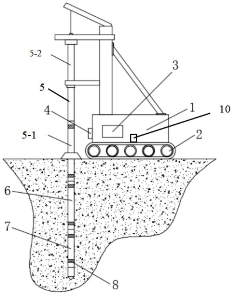
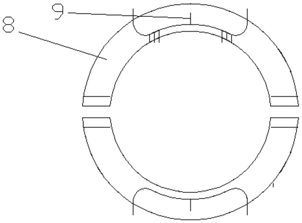
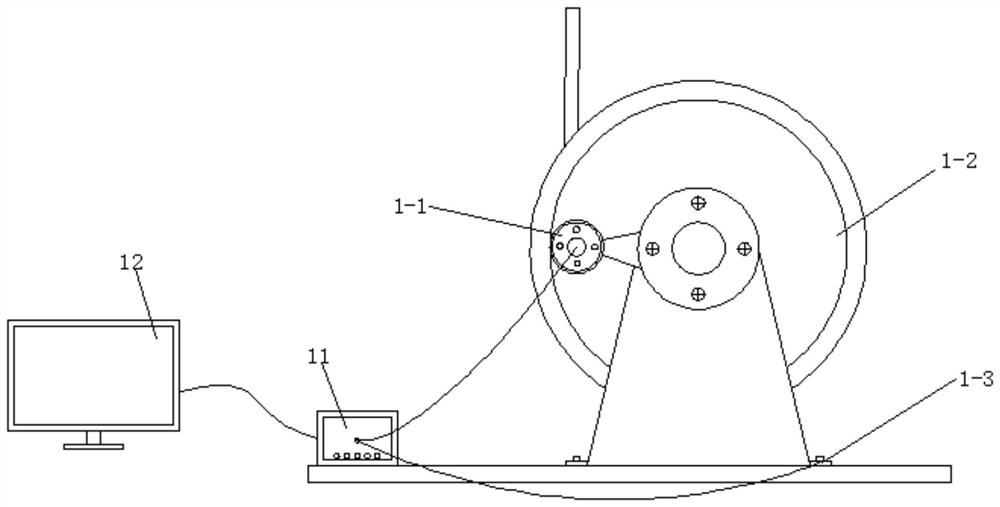
[0035] Such as Figure 1-3 As shown, a combined device for measuring the depth of a borehole includes a drilling rig body 1 and a crawler belt 2, an electronic meter counter 1-1 and a drilling rig hoisting shaft wheel 1-2 are arranged on the drilling rig body 1, and the drilling rig body 1 is provided with a positioning system module 10 at the bottom, and an integrated acquisition instrument 3 is provided on the front of the drilling rig body 1. The integrated acquisition instrument 3 is electrically connected to a data center, and the data center is electrically connected to the cloud platform. The drilling rig body 1 The base is equipped with a radio frequency coil 4, the radio frequency coil 4 can sense the passing of the metal buckle 8, the metal buckle 8 is installed on the drill pipe 5, and the active drill pipe 5-2 is installed above the drill pipe 5, an...


PUM


Abstract

The invention provides a combined type device for measuring drilling depth. The combined type device comprises a drilling machine body and a crawler belt, wherein an electronic meter counter and a drilling machine hoisting shaft wheel are arranged on the drilling machine body; a positioning system module is arranged at the bottom end of the drilling machine body; an integrated acquisition instrument is arranged on the front surface of the drilling machine body; the integrated acquisition instrument is electrically connected with a data center; the data center is electrically connected with a cloud platform; a radio frequency coil is mounted on a base of the drilling machine body; the radio frequency coil can sense passing of a metal buckle; the metal buckle is mounted on a drilling rod; a driving drilling rod is mounted above the drilling rod; a chip is mounted in the metal buckle; and an electronic label is arranged in the chip. By adopting the device and the method, the problems of an existing monitoring method that errors are great when the quantity of the drilling rods is manually counted, the working cost is high, the monitoring speed is slow, the working efficiency is low, the monitoring is difficult to realize, informatization is difficult to realize and the real-time performance is poor are solved.

Description

technical field [0001] The invention relates to the technical field of construction engineering, in particular to a combined device and method for measuring the depth of a borehole. Background technique [0002] The drill pipe is a steel pipe with threads at the end, which is used to connect the surface equipment of the drilling rig and the drilling and grinding equipment or the bottom hole device at the bottom of the drilling well. The purpose of the drill pipe is to transport the drilling mud to the drill bit and together with the drill bit to raise, lower or rotate the bottom hole device. Drill pipe must be able to withstand enormous internal and external pressure, twisting, bending and vibration. [0003] During the use of drill pipes, the drilling depth needs to be measured. The traditional measurement method is to manually count the number of drill pipes drilled. On the one hand, this method increases the workload of technicians, increases work costs, and affects labo...

Claims


Application Information

Patent Timeline
IPC IPC(8): E21B47/04E21B47/12E21B7/02E21B17/00
Inventor 王建强刁伟东蒋鹏练裕锋卢庆庆
Owner 深圳市城安物联科技有限公司
Learn More