Composite dielectric constant calculation method and system

A technology of dielectric constant and composite materials, applied in the direction of material capacitance, etc., can solve the problems of not considering the interface polarization of different materials, unable to conduct theoretical analysis, and unable to analyze the dielectric properties of materials, etc.

Active Publication Date: 2021-04-20
NORTH CHINA ELECTRIC POWER UNIV (BAODING)
View PDF17 Cites 4 Cited by
  • Summary
  • Abstract
  • Description
  • Claims
  • Application Information

AI Technical Summary

Problems solved by technology

In the diagnosis of the insulation state of materials, it is found that the dielectric parameters at low frequencies can better reflect the defects of materials, but the existing models for predicting the dielectric properties of multiphase composite materials mainly characterize the high-frequency dielectric properties of materials, and do not consider different materials. The interface polarization can only match the measured spectrum in the high frequency band, but there is a big difference in the middle and low frequency bands, and it is impossible to analyze the dielectric properties of the material at the middle and low frequencies.
In addition, dielectric materials with different structures need to be tested for dielectric response separately, which cannot be analyzed theoretically, and the operation is cumbersome and time-consuming

Method used


Image

  • Composite dielectric constant calculation method and system
  • Composite dielectric constant calculation method and system
  • Composite dielectric constant calculation method and system

Examples


Embodiment

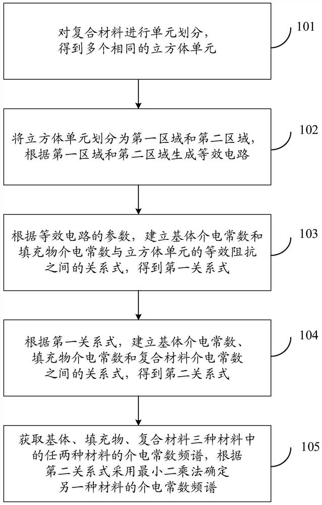
[0103] figure 1 It is a flow chart of the method for calculating the dielectric constant of composite materials in the embodiment of the present invention, such as figure 1 As shown, a method for calculating the dielectric constant of a composite material includes:

[0104] Step 101 : Divide the composite material into units to obtain a plurality of identical and independent cubic units; each cubic unit includes a filler located at the center of the cubic unit and a matrix disposed on the outer surface of the filler.

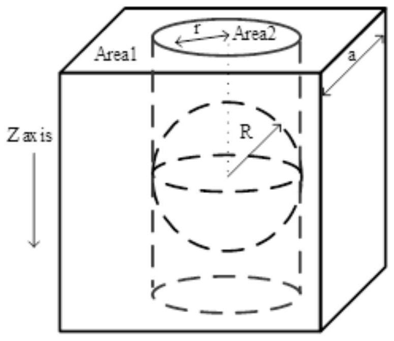
[0105] like figure 2As shown, the composite material is divided into m×n×h identical independent cubic units of size a×b×c. Each cube contains an arbitrary-shaped medium at the center. The embodiment of the present invention is a cube with a side length a, which contains a spherical medium with a radius R, the spherical medium in the middle of the cube is a filler, and the volume ratio of the spherical medium in the cube is equal to the volume ratio of the f...


PUM


Abstract

The invention discloses a method and a system for calculating the dielectric constant of a composite material. According to the method, the composite material is divided into independent cubic unit structures, the cubic structures are subjected to region division, interface polarization irregular regions are subjected to circuit equivalence, interface polarization between different materials is considered, the dielectric spectrum of a high frequency band can be calculated, and the dielectric spectrums of a medium frequency band and a low frequency band of the composite material can also be calculated; and by utilizing the second relational expression, the dielectric constant frequency spectrum of the composite material can be calculated according to the dielectric spectral lines of a matrix and a filler, and the dielectric constant frequency spectrum of the other material can be reversely deduced according to the composite material and the dielectric spectral line of one material, so that the workload is greatly reduced, and the test time is saved.

Description

technical field [0001] The invention relates to the technical field of material performance evaluation, in particular to a method and system for calculating the dielectric constant of composite materials. Background technique [0002] With the development of modern science and technology, many new composite dielectric materials have appeared in the power system, including nanoparticle filling materials, foam materials, fiber films, etc. The dielectric constant of the filler has a very important reference value, but due to the influence of the pores of the matrix material, it is impossible to separate the matrix and the filler for dielectric response tests to obtain the dielectric constant, so it is necessary to invert the composition through the overall dielectric spectrum. part of the dielectric spectrum. At the same time, the dielectric response test takes a long time. In order to quickly gain a preliminary understanding of the properties of the synthesized material, it i...

Claims


Application Information

Patent Timeline
Patent Type & Authority Applications(China)
IPC IPC(8): G01N27/22
Inventor 黄猛宋翰林吴延宇吕玉珍
Owner NORTH CHINA ELECTRIC POWER UNIV (BAODING)
Why Eureka
Try Eureka