Electromechanical equipment fault positioning system

A technology for fault location and electromechanical equipment, which is applied in the measurement of electricity, measurement of electrical variables, and testing of machine/structural components.

Inactive Publication Date: 2021-04-20
郑佳伟
View PDF1 Cites 0 Cited by
  • Summary
  • Abstract
  • Description
  • Claims
  • Application Information

AI Technical Summary

Problems solved by technology

[0004] However, the general fault diagnosis system is usually only aimed at a specific diagnostic object, while the expert system uses a large number of domain expert experience as its knowledge base and can complete the tasks in the professional field at the level of human experts and is applied in fault diagnosis. The fault diagnosis of different equipment can be completed by using the experience of experts in different fields as its knowledge base. However, the expert system has the weakness of difficult knowledge acquisition, and the representation of knowledge has an important impact on the design of various parts of the expert system, especially the inference engine.

Method used


Image

  • Electromechanical equipment fault positioning system
  • Electromechanical equipment fault positioning system
  • Electromechanical equipment fault positioning system

Examples


Embodiment 1

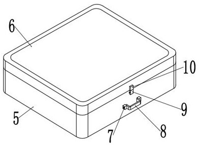
[0056] A fault location system for electromechanical equipment provided by the present invention includes a knowledge base 1 and a box body 5. One side of the top outer wall of the box body 5 is movably connected with a box cover 6 through a hinge, and one side of the box body 5 is installed with a screw through a screw. Detecting microcomputer 12, box body 5 is provided with a plurality of receiving grooves 16 near the side of testing microcomputer 12, and on the outer wall of box cover 6 close to the side of box body 5, rubber convex pad 11 fit inside box body 5 is bonded, box The center of the front outer wall of the body 5 and the case cover 6 is respectively welded with a lower positioning plate 9 and an upper positioning plate 10, and the center of the outer wall of the lower positioning plate 9 is provided with a slot 17, and the center of the inner wall on one side of the slot 17 is welded. There is a cylinder 20, and a tie rod 23 runs through the axis of the cylinder 2...


PUM


Abstract

The invention relates to the field of electromechanical equipment fault positioning, and aims at providing an electromechanical equipment fault positioning system which comprises a knowledge base and a box body. One side of the outer wall of the top of the box body is movably connected with a box cover through a hinge, a detection microcomputer is installed on one side in the box body through screws, a plurality of storage grooves are formed in the side, close to the detection microcomputer, of the box body, and a rubber convex pad matching the interior of the box body is bonded to the outer wall of the side, close to the box body, of the box cover. The system has the beneficial effects that a hybrid reasoning strategy is adopted, firstly, case-based reasoning is adopted to obtain a historical fault source of the fault phenomenon, if the historical fault source does not exist, rule-based reasoning is adopted to obtain a possible fault component, reverse reasoning is carried out to obtain a sign which can be caused by the fault component, and if the fault sign is confirmed through interactive inquiry, the fault source is confirmed, otherwise, reverse reasoning is carried out on the next possible fault source until the fault component is confirmed.

Description

technical field [0001] The invention relates to the field of electromechanical equipment fault location, in particular to a electromechanical equipment fault location system. Background technique [0002] Electromechanical equipment refers to equipment composed of machinery and electronics. The goal of working is achieved by electronically controlling mechanical devices, which is a symbol of industrialization. Mechanical and electrical equipment generally includes various mechanical processing equipment, automated production lines, industrial robots used in the machinery manufacturing industry, and mechanical equipment used in other industries, such as textile machinery, mining machinery, etc. [0003] According to the Inspection Institute, Chinese Patent No. CN109658954A provides a fault detection method for electromechanical equipment. Since the sound of electromechanical equipment in normal operation is generally different from the sound of failure, it is only necessary t...

Claims


Application Information

Patent Timeline
Patent Type & Authority Applications(China)
IPC IPC(8): G01R31/56G01M99/00
Inventor 郑佳伟
Owner 郑佳伟
Why Eureka
Try Eureka