Anti-scratch high-strength aluminum alloy cable bridge connecting device

A technology for cable bridges and connecting devices, which is applied in the direction of electrical components, etc., and can solve problems such as cable sheath scratches, cable scratches, and leakage

Inactive Publication Date: 2021-04-20
ANHUI HUAXI ELECTRIC POWER TECH CO LTD
View PDF8 Cites 0 Cited by
  • Summary
  • Abstract
  • Description
  • Claims
  • Application Information

AI Technical Summary

Problems solved by technology

[0003] The existing bridges usually use connecting devices to connect the two bridges in the vertical direction at the joints at right angles, while the traditional bridge connectors use anchor bolts or bolts and nuts to connect the bridges together, whic

Method used


Image

  • Anti-scratch high-strength aluminum alloy cable bridge connecting device
  • Anti-scratch high-strength aluminum alloy cable bridge connecting device
  • Anti-scratch high-strength aluminum alloy cable bridge connecting device

Examples


Embodiment 1

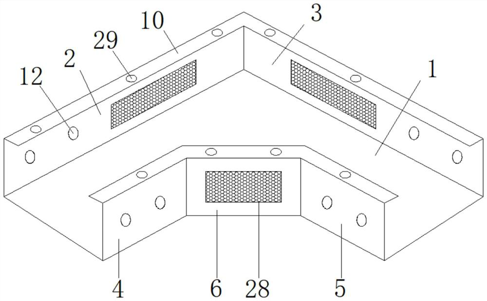
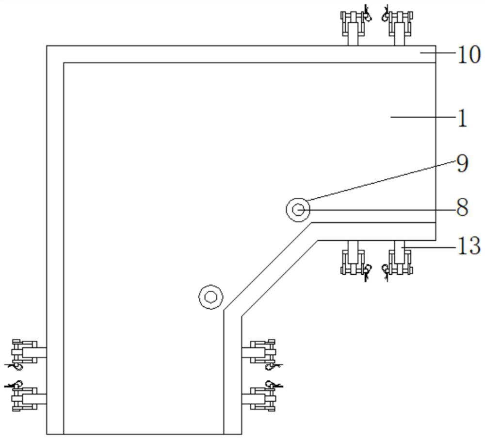
[0031] see Figure 1-9 According to an embodiment of the present invention, an anti-scratch high-strength aluminum alloy cable tray connection device includes a bottom plate 1, a first side plate 2 and a second side plate 3 are fixed on the outer side of the bottom plate 1, and the first side plate 2 is fixed on the outer side of the bottom plate 1. One side plate 2 is vertically arranged with the second side plate 3, and a third side plate 4 and a fourth side plate 5 are fixed on the inner side of the bottom plate 1, and the third side plate 4 and the fourth side plate A fifth side plate 6 is fixed between the 5, and the fifth side plate 6 is fixed on the inner side of the bottom plate 1, and two bearings 7 are fixedly embedded on the bottom plate 1, and the bearings 7 are arranged on the inner side of the intersection of the third side plate 4, the fourth side plate 5 and the fifth side plate 6 respectively, and a rotating shaft 8 is fixed inside the bearing 7, and the outer...

Embodiment 2

[0034] see Figure 1-2 , for the third side plate 4, the fourth side plate 5 and the fifth side plate 6, the angle between the third side plate 4, the fourth side plate 5 and the fifth side plate 6 are all 135°; for the first side plate, the second side plate and the fifth side plate 6, the middle parts of the first side plate 2, the second side plate 3 and the fifth side plate 6 are all opened There are heat dissipation windows 28, and dustproof nets are fixedly installed in the heat dissipation windows 28.

[0035] Through the above solution of the present invention, the heat dissipation window 28 can effectively increase the heat dissipation performance of the cable in the connection device, and the dust-proof net can prevent dust from entering the connection device, thereby preventing dust from falling on the cable surface and affecting the normal heat dissipation of the cable.

Embodiment 3

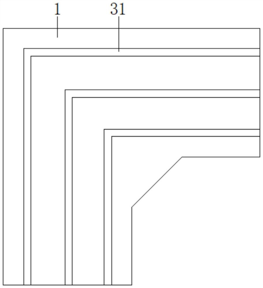
[0037] see figure 1 , 3 and 4, for the curling 10, the curling 10 is fixedly embedded with a plurality of first magnets 29, and the dust cover 11 is fixedly embedded with a plurality of second magnets 30 matching the first magnets 29 ; For the bottom plate 1, the first side plate 2, the second side plate 3, the third side plate 4, the fourth side plate 5, the fifth side plate 6, the bottom plate 1, the first side plate 2, The second side plate 3 , the third side plate 4 , the fourth side plate 5 , the fifth side plate 6 and the curling 10 are all made of aluminum alloy material and have an integrated structure; As for the base plate 1 , several reinforcing ribs 31 are fixedly arranged under the base plate 1 .

[0038] Through the above scheme of the present invention, the first magnet 29 and the second magnet 30 can effectively absorb and fix the dust cover 11, and can facilitate the disassembly of the dust cover 11. The aluminum alloy has high mechanical strength, and the r...


PUM


Abstract

The invention discloses an anti-scratch high-strength aluminum alloy cable bridge connecting device. The device comprises a bottom plate, a first side plate and a second side plate are fixedly arranged on the outer side of the bottom plate, the first side plate is perpendicular to the second side plate, and a third side plate and a fourth side plate are fixedly arranged on the inner side of the bottom plate. A fifth side plate is fixedly arranged between the third side plate and the fourth side plate, the fifth side plate is fixed to the inner side of the bottom plate, two bearings are fixedly embedded in the bottom plate, and the bearings are arranged on the inner sides of the joints of the third side plate, the fourth side plate and the fifth side plate correspondingly. And a rotating shaft is fixedly arranged in the bearing. The device has the beneficial effects that tools are not needed during installation, so that the bridge and the connecting device can be conveniently installed, the cable can be effectively prevented from being scratched at the corner, and the cable can be protected.

Description

technical field [0001] The invention relates to the field of bridge connection, in particular to a scratch-resistant high-strength aluminum alloy cable bridge connection device. Background technique [0002] Cable trays are divided into trough type, tray type, ladder frame type, grid type and other structures, and are composed of brackets, supporting arms and installation accessories. It can be erected independently, and can also be laid on various buildings (structures) and pipe gallery supports. It reflects the characteristics of simple structure, beautiful appearance, flexible configuration and convenient maintenance. All parts need to be galvanized and installed in buildings. If the bridge frame in the open air is near the sea or belongs to the corrosion area, the material must have the physical characteristics of anti-corrosion, moisture resistance, good adhesion, and high impact resistance. [0003] The existing bridges usually use connecting devices to connect the tw...

Claims


Application Information

Patent Timeline
IPC IPC(8): H02G3/06H02G3/03H02G3/04
Inventor 侯尽然李陆军张文冰许春雷龚盼盼张志刚蒋跃跃翟慧阳
Owner ANHUI HUAXI ELECTRIC POWER TECH CO LTD
Why Eureka
Try Eureka