Eureka AIR delivers breakthrough ideas for toughest innovation challenges, trusted by R&D personnel around the world.

C-shaped tooth permanent magnet linear motor with double-stator arc-shaped and auxiliary groove mixed structure

A permanent magnet linear motor, hybrid structure technology, applied in the magnetic circuit shape/style/structure, electrical components, electromechanical devices, etc., can solve the problems of large positioning force, axial length limitation, small inertia of the mover, etc.

Active Publication Date: 2021-04-20
SOUTHEAST UNIV
View PDF5 Cites 0 Cited by
  • Summary
  • Abstract
  • Description
  • Claims
  • Application Information

AI Technical Summary

Problems solved by technology

When the motor uses a single permanent magnet as the mover, the mover inertia is small, and the positioning force can be ignored within the effective stroke, but the shortcomings of its relatively small output force and the effective stroke being limited by the axial length of the motor cannot be ignored.
When using three permanent magnet structures, although the output force has been greatly improved, the larger positioning force affects the quality of the output force and increases the difficulty of motor control.

Method used


Image

  • C-shaped tooth permanent magnet linear motor with double-stator arc-shaped and auxiliary groove mixed structure
  • C-shaped tooth permanent magnet linear motor with double-stator arc-shaped and auxiliary groove mixed structure
  • C-shaped tooth permanent magnet linear motor with double-stator arc-shaped and auxiliary groove mixed structure

Examples


Embodiment Construction

[0032] The following will clearly and completely describe the technical solutions in the embodiments of the present invention with reference to the accompanying drawings in the embodiments of the present invention. Obviously, the described embodiments are only some, not all, embodiments of the present invention. Based on the embodiments of the present invention, all other embodiments obtained by persons of ordinary skill in the art without creative efforts fall within the protection scope of the present invention.

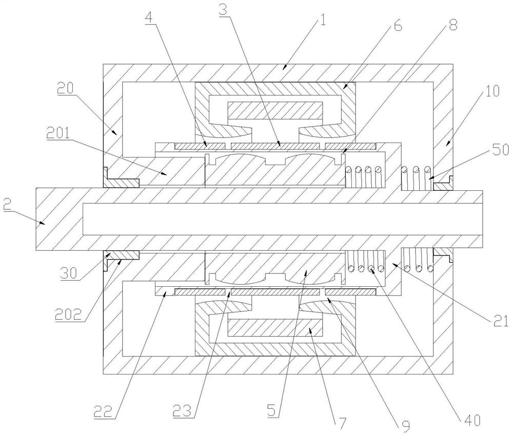
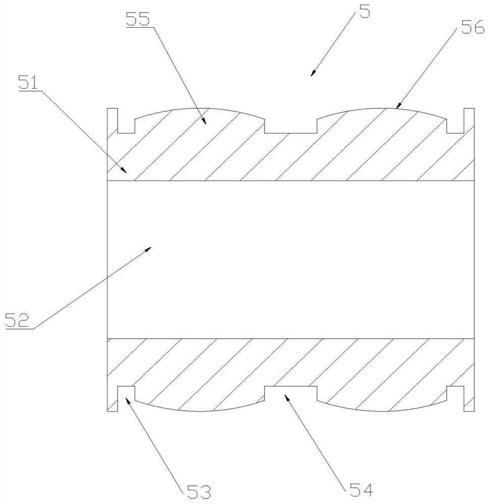
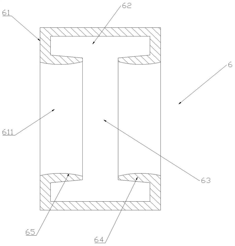
[0033] A C-shaped tooth permanent magnet linear motor with a mixed structure of double stator arcs and auxiliary slots. The permanent magnet linear motor includes a housing 1, such as figure 1 As shown, the housing 1 is slidingly provided with an output shaft 2, and the housing 1 is fixedly provided with an inner stator 5, the inner stator 5 is set on the output shaft 2, the output shaft 2 is provided with a support ring 21, and the support ring 21 is provided with ...


PUM


Abstract

The invention discloses a C-shaped tooth permanent magnet linear motor with a double-stator arc-shaped and auxiliary groove mixed structure, and the permanent magnet linear motor comprises a housing, an output shaft is slidingly disposed in the housing, an inner stator is fixedly disposed in the housing, the inner stator sleeves the output shaft, a support ring is disposed on the output shaft, and a rotor iron core is disposed on the support ring. A first permanent magnet and a second permanent magnet that are symmetrically distributed are arranged in the rotor iron core, an outer stator is fixed on the inner wall of the housing, and an armature winding is arranged in the outer stator; the rotor of the permanent magnet linear motor is of a three-permanent-magnet structure, and compared with a traditional single-permanent-magnet structure, the larger output force is provided; compared with a traditional double-stator motor, three auxiliary grooves are formed in the inner stator, the length of the inner stator is shortened, the total mass of the motor is reduced, the material cost of the motor is reduced, and the power density of the motor is improved; compared with a motor with an unoptimized inner stator, the positioning force of the motor is greatly reduced, and meanwhile, the motor has a longer effective stroke.

Description

technical field [0001] The invention relates to the technical field of motors, in particular to a C-shaped tooth permanent magnet linear motor with a mixed structure of double stator arcs and auxiliary slots. Background technique [0002] The traditional compressor drive technology mostly uses rotating motors to connect cranks and shafts, ball screws and other driving methods. Due to mechanical friction and energy transmission during the transmission process, the efficiency is low, and the complex mechanical structure also reduces the reliability and reliability of the system. Increased maintenance difficulty. The linear motor saves the complicated mechanical structure in the compressor because of its unique motion mode, which not only reduces the cost, simplifies the system structure, but also increases the reliability and efficiency of the system. [0003] Among the linear oscillating motors, the permanent magnet linear oscillating motor has been widely concerned and used...

Claims


Application Information

Patent Timeline
IPC IPC(8): H02K41/03H02K16/04H02K1/12H02K1/27
Inventor 金龙张洪彬余海涛徐志科
Owner SOUTHEAST UNIV
Why Eureka
Eureka Blog
Learn More