Purging structure special for rolling mill

A rolling mill and bottom plate technology, which is applied in the field of special purging structure for rolling mills, can solve problems such as poor purging effect, and achieve the effect of promoting cleaning, improving efficiency and expanding area

Active Publication Date: 2021-04-23
ZHEJIANG CHUANBOZHE METAL DECOUATION MATERIAL CO LTD
View PDF12 Cites 0 Cited by
  • Summary
  • Abstract
  • Description
  • Claims
  • Application Information

AI Technical Summary

Problems solved by technology

[0004] Although the overall device can purge the emulsion, in the process of purging, part of the emulsion will be blown to the edges of both sides of the material strip and stay at the edge, which will lead to a relatively poor purging effect. Therefore, it is urgently needed a Special purging structure for rolling mill

Method used


Image

  • Purging structure special for rolling mill
  • Purging structure special for rolling mill
  • Purging structure special for rolling mill

Examples


Embodiment 1

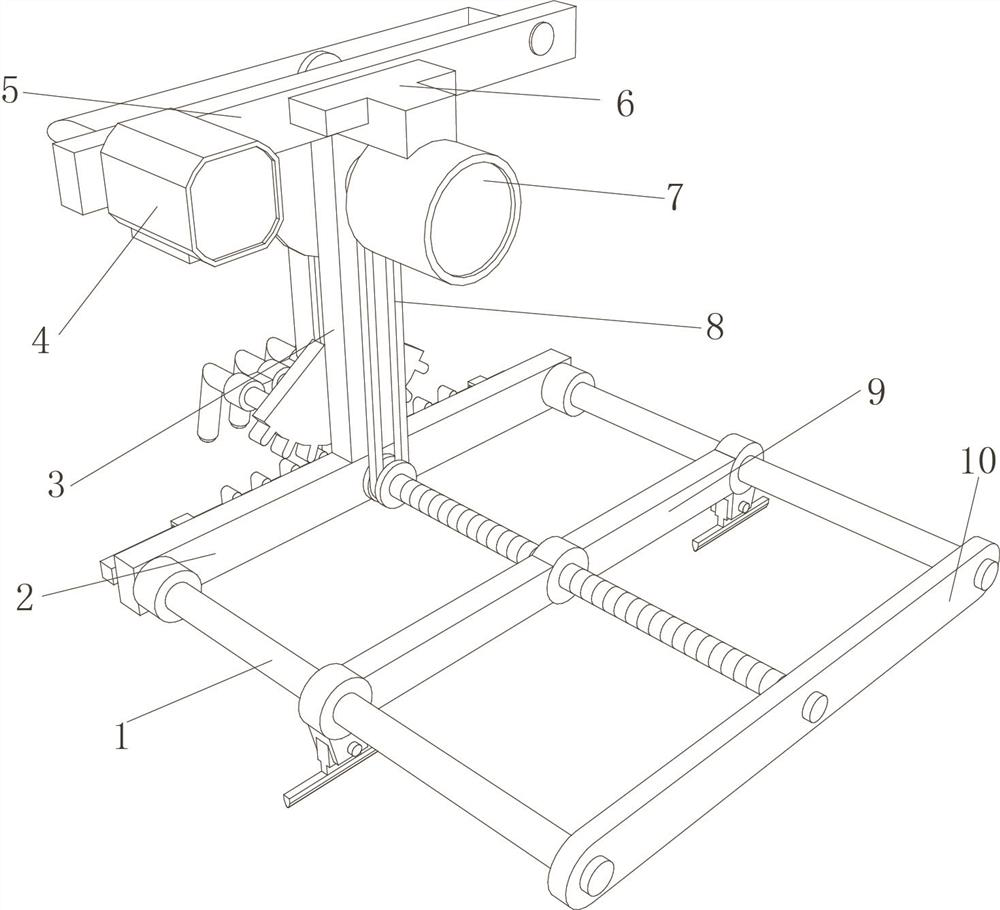
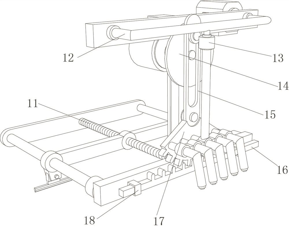
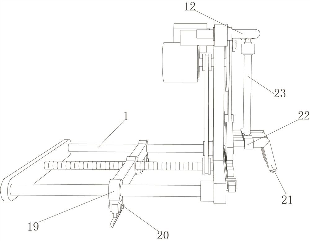
[0033] Rolling mill special purging structure, such as Figure 1-4As shown, it includes a base plate 2, a fixed plate 3 and a top plate 5. The outer wall on the opposite side of the bottom plate 2 and the top plate 5 is connected by the fixed plate 3, and the outer wall on one side of the top plate 5 is fixed with a support plate 6 by bolts. The outer wall of the bottom is fixed with a motor 7 by bolts, and the output end of the motor 7 is connected with a swing blowing mechanism through threads, and the outer wall of the bottom plate 2 near the bottom of the motor 7 is fixed with a screw rod 11 through a bearing, and the screw rod 11 and the output end of the motor 7 are respectively sleeved. Pulleys are connected, and the outer walls of the two pulleys are sleeved with the same transmission belt 8, and the outer walls of the ends of the bottom plate 2 near both sides of the screw rod 11 are respectively connected with guide rods 1 through threaded fixing rings, and the two gu...

Embodiment 2

[0038] Rolling mill special purging structure, such as Figure 5 As shown, in order to improve the effect of blowing air out of the trachea 21; this embodiment makes the following improvements on the basis of Embodiment 1: each of the trachea 21 is bonded with heating guide boxes 26 distributed equidistantly, and each The inside of the heating guide box 26 is filled with solid mixed sodium, and the inner wall of the output end of each air pipe 21 is bonded with an I-shaped air guide ring 27 and an air nozzle 28; when the air passes through the inside of the air pipe 21, the solid mixture in the heating guide box 26 The sodium element in sodium will react with oxygen to produce sodium peroxide, and absorb water vapor to release heat, thereby effectively heating the passing air, and then when the heated air passes through the I-shaped air guide ring 27, due to the narrow diameter of the middle port , which effectively promotes the accelerated flow of hot air, and is finally expo...


PUM


Abstract

The invention discloses a purging structure special for a rolling mill, and relates to the technical field of rolling mill purging. In order to achieve the aim of pursing emulsion, the purging structure specifically comprises a bottom plate, a fixing plate and a top plate, the outer walls of the opposite sides of the bottom plate and the top plate are connected through the fixing plate, a supporting plate is fixed to the outer wall of one side of the top plate through bolts, a motor is fixed to the outer wall of the bottom of the supporting plate through bolts, and the output end of the motor is in threaded connection with a swing purging mechanism; a screw is fixed to the outer wall of the side, close to the lower portion of the motor, of the bottom plate through a bearing, the screw and the output end of the motor are sleeved with belt wheels correspondingly, the circumferential outer walls of the two belt wheels are sleeved with the same transmission belt, and the outer walls of the ends, close to the two sides of the screw, of the bottom plate are connected with guide rods through threaded fixing rings correspondingly; and the end parts of the two guide rods and the screw are respectively sleeved with the same limiting plate. According to the purging structure, the cleaning of a cleaning assembly on the emulsion blown to the two sides of a material belt by the swing purging mechanism is effectively promoted, and the cleaning quality of the emulsion on the end face of the material belt is guaranteed.

Description

technical field [0001] The invention relates to the technical field of rolling mill purging, in particular to a special purging structure for rolling mills. Background technique [0002] The emulsion plays a role of lubrication and cooling in the steel rolling process, but the surface of the strip on the strip after rolling must be purged with air to remove the emulsion on the surface. On the other hand, cold rolling is a steel plate in which the steel plate is further thinned to a target thickness below the recrystallization temperature at room temperature. Compared with hot-rolled steel sheets, the thickness of cold-rolled steel sheets is more accurate, and the surface is smooth and beautiful. [0003] After searching, the Chinese patent application number is CN201610939553.2, which discloses a rolling mill strip processing purging device, including a movable guide plate, a purging device, an air inlet pipe, a connecting pipe, a rotating wheel, a blade, an air outlet hole...

Claims


Application Information

Patent Timeline
Patent Type & Authority Applications(China)
IPC IPC(8): B21B45/02
CPCB21B45/0284B21B45/0281Y02P70/10
Inventor 石付宗叶寿喜许路坤谢舍东童秋明田超周忠飞金伟建舒智广扬美琴鲍传宝
Owner ZHEJIANG CHUANBOZHE METAL DECOUATION MATERIAL CO LTD
Why Eureka
Try Eureka