A vertical wall pouring trolley

A technology of vertical walls and trolleys, which is applied in construction, infrastructure engineering, etc., can solve the problems of high labor intensity, high labor cost, and concrete grout leakage, and improve construction efficiency, safety, flexibility, and applicability Improve the effect of fast and accurate installation in place

Active Publication Date: 2022-07-15
河北东风世景轨道有限公司
View PDF0 Cites 0 Cited by
  • Summary
  • Abstract
  • Description
  • Claims
  • Application Information

AI Technical Summary

Problems solved by technology

This method involves a large amount of lap jointing of copper pipe supports and slow lap speed. When installing wooden formwork, the operating space is narrow, the working environment is poor, and the formwork assembly speed is slow. It is difficult to guarantee the quality of formwork and copper pipe support lap joints, and the reliability is poor. It is easy to cause side wall deformation or concrete grout leakage, wooden formwork assembly times are too many, concrete surface flatness is poor, joints are prone to misalignment, wooden formwork and its brackets and other turnover materials take a long time to dismantle, the turnover speed is slow, and the usage is large ; High technical requirements for workers, high labor intensity, large number of required workers, low efficiency and high labor costs
[0003] The existing pouring trolley has been greatly perfected and improved in terms of the integration of formwork and the movement and fixation of the trolley. However, for the fixing of the sealing plates at both ends of the formwork, workers still fasten them layer by layer on the edge of the formwork. For installation and fixing, it is necessary to work on a trolley or concrete reinforcement, which is a heavy workload and high risk

Method used


Image

  • A vertical wall pouring trolley
  • A vertical wall pouring trolley
  • A vertical wall pouring trolley

Examples


Embodiment Construction

[0042] In order to make the purpose, technical solutions and advantages of the present invention clearer, the invention will be clearly and completely described below in conjunction with specific embodiments. It should be understood that the terms "center", "vertical", "horizontal", "upper" , "bottom", "front", "back", "left", "right", "vertical", "horizontal", "top", "bottom", "inside", "outer", etc. The positional relationship is based on the orientation or positional relationship shown in the accompanying drawings, which is only for the convenience of describing the present invention and simplifying the description, rather than indicating or implying that the referred device or element must have a specific orientation, be constructed and operated in a specific orientation, Therefore, it should not be construed as a limitation of the present invention.

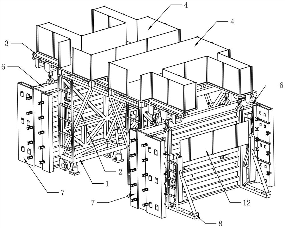
[0043] like figure 1 A vertical wall pouring trolley shown is used for pouring two vertical walls at the same time, which i...


PUM


Abstract

The invention relates to the field of pouring trolleys, in particular to a vertical wall pouring trolley, which includes two sets of pouring systems arranged symmetrically, the pouring systems include a running system for driving the pouring systems to move, and is fixed on the running system. The support structure on the system, the pulley guide rail arranged on the support structure, the lifting pulley system slidably installed on the pulley guide rail, the formwork system connected with the rope of the lifting pulley system, set on the formwork system Automatic sealing plate system on both sides, used to fix and support the support formwork system of the formwork system. The invention does not need to build a copper pipe bracket and an assembly template, has fast installation speed, stable structure, convenient adjustment of the thickness of the vertical wall, convenient dismantling and maintenance of parts and components, and can realize the automatic completion of the sealing plate.

Description

technical field [0001] The invention relates to the field of pouring trolleys, in particular to a vertical wall pouring trolley. Background technique [0002] The traditional vertical wall concrete construction generally adopts the wooden formwork construction method of the full-house bracket method. This process requires the construction of copper pipe supports with the same width as the foundation pit in the foundation pit, and then the wooden formwork is assembled piece by piece. This method has a large amount of lap jointing of copper pipe supports, slow lap joint speed, narrow operating space, poor working environment, slow formwork assembly speed, difficult to guarantee the lap joint quality of formwork and copper pipe brackets, poor reliability, and poor concrete pouring during the installation of wooden formwork. It is easy to cause side wall deformation or concrete leakage, many times of wood formwork assembly, poor flatness of concrete surface, easy to have joint m...

Claims


Application Information

Patent Timeline
Patent Type & Authority Patents(China)
IPC IPC(8): E02D15/02
CPCE02D15/02
Inventor 王立强刘工念史悦军杨飞张金国
Owner 河北东风世景轨道有限公司
Why Eureka
Try Eureka