
Curtain wall for constructional engineering

A construction engineering and curtain wall technology, applied in construction, building maintenance, building components, etc., can solve the problems of time-consuming, labor-intensive, lack of heat insulation and cooling effect, etc.

Inactive Publication Date: 2021-04-23
平国文
View PDF11 Cites 1 Cited by
  • Summary
  • Abstract
  • Description
  • Claims
  • Application Information

AI Technical Summary

Problems solved by technology

[0003] The existing patent (notification number: CN 104234283 B) discloses a double-layer curtain wall, including: an outer curtain wall, an inner curtain wall, a building main body, cantilever rods and cables; the inner curtain wall is fixed on the building main body Above, the outer curtain wall is located on the outer side of the inner curtain wall; the cable is located between the inner curtain wall and the outer curtain wall, and is arranged in a vertical direction, and its two ends are respectively connected to the main body of the building fixed; the cantilever rod includes a front rod and a rear rod, and the front rod and the rear rod are fixed through the ends, and a through hole is provided at the joint for the stay cable to pass through, and the stay cable remains in a tight state The other end of the rear bar is fixed to the main body of the building, and the other end of the front bar is fixed to the outer curtain wall. The inventors have found that at least the following problems have not been solved in the prior art: 1. The double-layer The curtain wall does not have the effect of heat insulation and cooling when the sunlight is strong; 2. The double-layer curtain wall needs to be wiped and cleaned manually, which is time-consuming and laborious

Method used


Image

  • Curtain wall for constructional engineering
  • Curtain wall for constructional engineering
  • Curtain wall for constructional engineering

Examples


Embodiment Construction

[0024] In order to make the technical means, creative features, goals and effects achieved by the present invention easy to understand, the present invention will be further described below in conjunction with specific embodiments.

[0025] In the description of the present invention, it should be noted that the terms "upper", "lower", "inner", "outer", "front end", "rear end", "both ends", "one end", "another end" The orientation or positional relationship indicated by etc. is based on the orientation or positional relationship shown in the drawings, and is only for the convenience of describing the present invention and simplifying the description, rather than indicating or implying that the referred device or element must have a specific orientation, use a specific Azimuth configuration and operation, therefore, should not be construed as limiting the invention. In addition, the terms "first" and "second" are used for descriptive purposes only, and should not be understood ...


PUM


Abstract

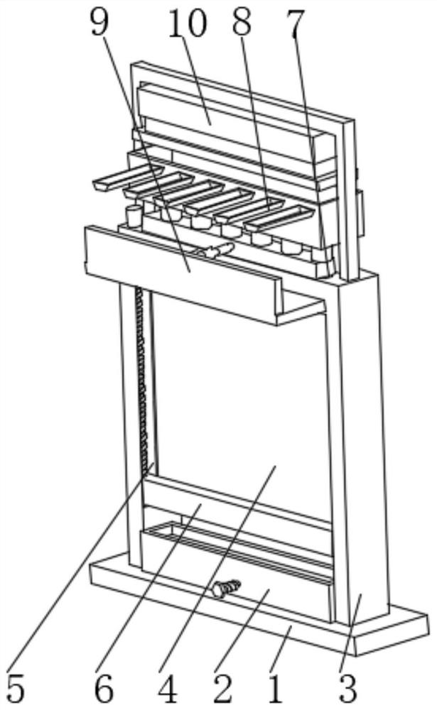
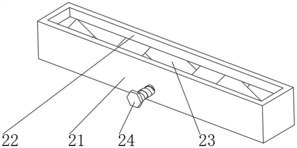
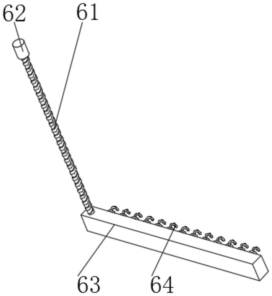
The invention discloses a curtain wall for constructional engineering. The curtain wall comprises a base, a collecting device is arranged in the middle of the upper end of the base, a frame is fixedly installed at the upper end of the base, the curtain wall is fixedly installed on the upper part of an inner cavity of the frame, a sliding groove is formed in the left wall of the inner cavity of the frame, a sliding cleaning device is arranged on the groove wall of the sliding groove, a plurality of groups of through holes are formed in the front part of the upper end of the frame, a water collecting device is arranged at the rear part of the upper end of the frame, a telescopic blocking device is arranged on the upper part of the front end of the frame, and an expansion extrusion device is arranged at the upper end of the frame. According to the curtain wall for constructional engineering, a heat conduction box absorbs solar heat and conducts the solar heat to a plastic block, the plastic block has a heat expansion and cold contraction effect, when the plastic block is heated and is in an expansion state, an extrusion plate is driven to move downwards to enter a water collecting groove, water is extruded, the flowing speed of the water is increased, so that the water can rapidly drive heat, and the heat insulation and cooling effects are improved.

Description

technical field [0001] The invention relates to the field of curtain wall equipment, in particular to a curtain wall for construction engineering. Background technique [0002] The curtain wall is the outer wall enclosure of the building. It is not load-bearing and hangs up like a curtain, so it is also called "curtain wall". It is a light-weight wall with decorative effect commonly used in modern large-scale and high-rise buildings. Composed of panels and supporting structure systems, it can have a certain displacement capacity relative to the main structure or a certain deformation capacity itself, and does not bear the role of the main structure. The building envelope structure or decorative structure (the external wall frame support system is also a curtain wall system One of the common glass curtain wall structures: hidden frame, semi-hidden frame, exposed frame, point type, full glass, etc. The curtain wall can be divided into: building curtain wall, component building...

Claims


Application Information

Patent Timeline
Patent Type & Authority Applications(China)
IPC IPC(8): E04B2/96E04G23/00
CPCE04B2/96E04G23/002
Inventor 平国文
Owner 平国文
Learn More