Pipeline connection joint applied to on-site maintenance

A technology for pipeline connection and on-site maintenance, applied in the direction of pipes/pipe joints/fittings, pipe components, mechanical equipment, etc., can solve problems such as inconvenient maintenance of rubber pipes

Active Publication Date: 2021-04-23
INST OF ENG MECHANICS CHINA EARTHQUAKE ADMINISTRATION
View PDF10 Cites 0 Cited by
  • Summary
  • Abstract
  • Description
  • Claims
  • Application Information

AI Technical Summary

Problems solved by technology

[0003] In view of this, the object of the present invention is to provide an on-site maintenance pip

Method used


Image

  • Pipeline connection joint applied to on-site maintenance
  • Pipeline connection joint applied to on-site maintenance
  • Pipeline connection joint applied to on-site maintenance

Examples


Embodiment

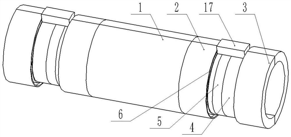
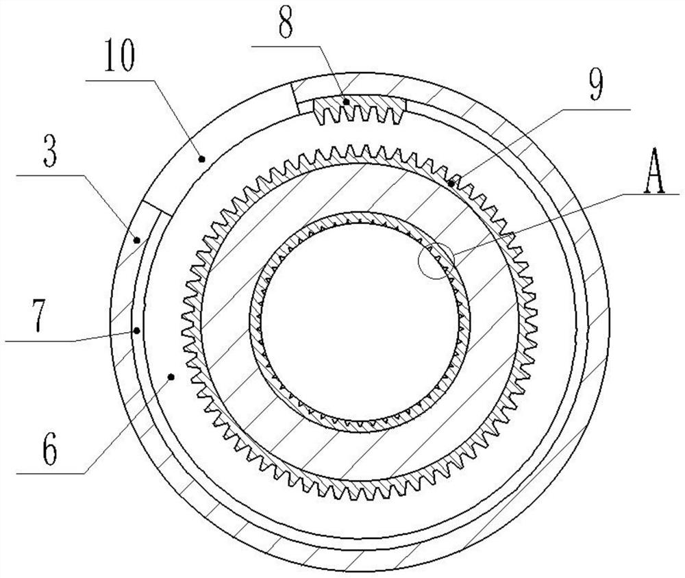
[0033] A field serviceable line connection fitting such as Figure 1-Figure 9 As shown, it includes a connecting cylinder 1 and welding cylinders arranged at both ends of the connecting cylinder 1 .

[0034] The fusion barrel includes a first side pipe 3 and a second side pipe 2 , and the second side pipe 2 is fixedly connected with the connection barrel 1 . The first side pipe 3, the second side pipe 2 and the connecting cylinder 1 are all composed of two half-rings, that is, the three can be disassembled into two half-rings, and can be combined into a whole ring by bolts. A welding ring 4 is fixedly arranged between the first side pipe 3 and the second side pipe 2 , and a vacuum groove 19 is provided on a part of the inner wall of the welding ring 4 close to the first side pipe 3 . The vacuum groove 19 is annular and concentric with the second welding ring 4. The vacuum groove 19 is sealed with an annular plastic strip 18. The melting temperature of the plastic strip 18 is ...


PUM


Abstract

The invention relates to the field of pipelines, in particular to a pipeline connection joint applied to on-site maintenance. The pipeline connection joint comprises a connecting barrel, and melting barrels which are arranged at the two ends of the connecting barrel, wherein each of the melting barrels comprises a first side pipe and a second side pipe; the corresponding second side pipe is connected with the connecting barrel; a melting ring is arranged between the each first side pipe and the each second side pipe; a vacuum groove is formed in the corresponding melting barrel and is annular-shaped; the vacuum grooves are sealed by using plastic strips, the melting temperatures of the plastic strips are more than the temperatures of pipelines; a conical groove communicates with the inner wall of the each vacuum groove, and one end, with smaller width, of the each conical groove faces the vacuum grooves; and annular cutting grooves are also formed in the melting rings, cutting rings are rotatably and concentrically arranged in the cutting grooves, mounting grooves are also formed in the inner walls of the cutting rings, springs are arranged in the mounting grooves, and cutters are arranged on the springs. The technical problem of inconvenience in maintenance of rubber pipelines is solved.

Description

technical field [0001] The invention relates to the field of pipelines, and specifically discloses an on-site maintenance pipeline connection joint. Background technique [0002] At present, large-scale engineering projects such as long-distance gas transmission, liquid infusion, and cables all need to use large-scale pipelines, and the materials of these pipelines include metal, rubber, plastic, etc. Pipelines may be damaged by earthquakes, corrosion, landslides, etc., resulting in leakage of the conveying medium, or exposure of cables and optical cables, requiring immediate repair or replacement. However, due to the large size of the pipeline, maintenance is difficult. Contents of the invention [0003] In view of this, the object of the present invention is to provide an on-site maintenance pipeline connection joint to solve the technical problem of inconvenient maintenance of rubber pipelines. [0004] To achieve the above object, the present invention provides the fo...

Claims


Application Information

Patent Timeline
IPC IPC(8): F16L55/16B29C65/74B29C65/34
Inventor 孙得璋何先龙张昊宇李思汉戴君武
Owner INST OF ENG MECHANICS CHINA EARTHQUAKE ADMINISTRATION
Why Eureka
Try Eureka