
Nitrogen blowing assembly of solid-phase extraction nitrogen blowing concentrator

A concentrator and nitrogen blowing technology, applied in the field of separation, can solve the problems of waste of manpower and material resources, rough constant volume accuracy, and inability to extract samples

Pending Publication Date: 2021-04-23
湖北鼎泰高科有限公司
View PDF10 Cites 0 Cited by
  • Summary
  • Abstract
  • Description
  • Claims
  • Application Information

AI Technical Summary

Problems solved by technology

[0004] At present, solid-phase extraction instruments can complete the function of sample collection, but they cannot extract large quantities of samples. If large quantities of samples need to be processed, repeated extractions are required, resulting in a cumbersome process and a waste of manpower and material resources. , it needs to be transferred to a special constant volume concentrator for constant volume concentration to be suitable for subsequent analysis instruments. At present, the more common constant volume concentrators include automatic water bath nitrogen blowing concentrator and rotary evaporator
There are many defects in this constant volume concentration method. First, the sample is prone to sample loss and air contact during the transfer process, resulting in pollution problems; Specifications Requiring Quick Change Nitrogen Blowing Components
[0005] Obviously, this method of constant volume can easily cause the sample to be evaporated to dryness during nitrogen blowing or rotary evaporation, resulting in a waste of experiments, and the open nitrogen blowing device is extremely harmful to the health of operators

Method used


Image

  • Nitrogen blowing assembly of solid-phase extraction nitrogen blowing concentrator
  • Nitrogen blowing assembly of solid-phase extraction nitrogen blowing concentrator
  • Nitrogen blowing assembly of solid-phase extraction nitrogen blowing concentrator

Examples


Embodiment Construction

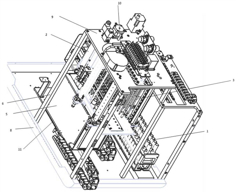
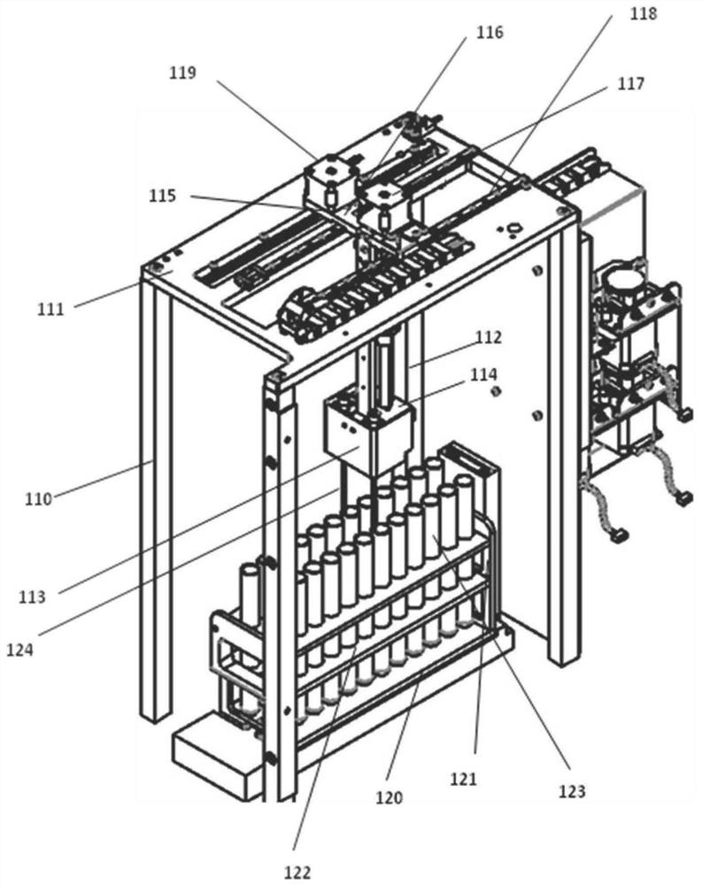
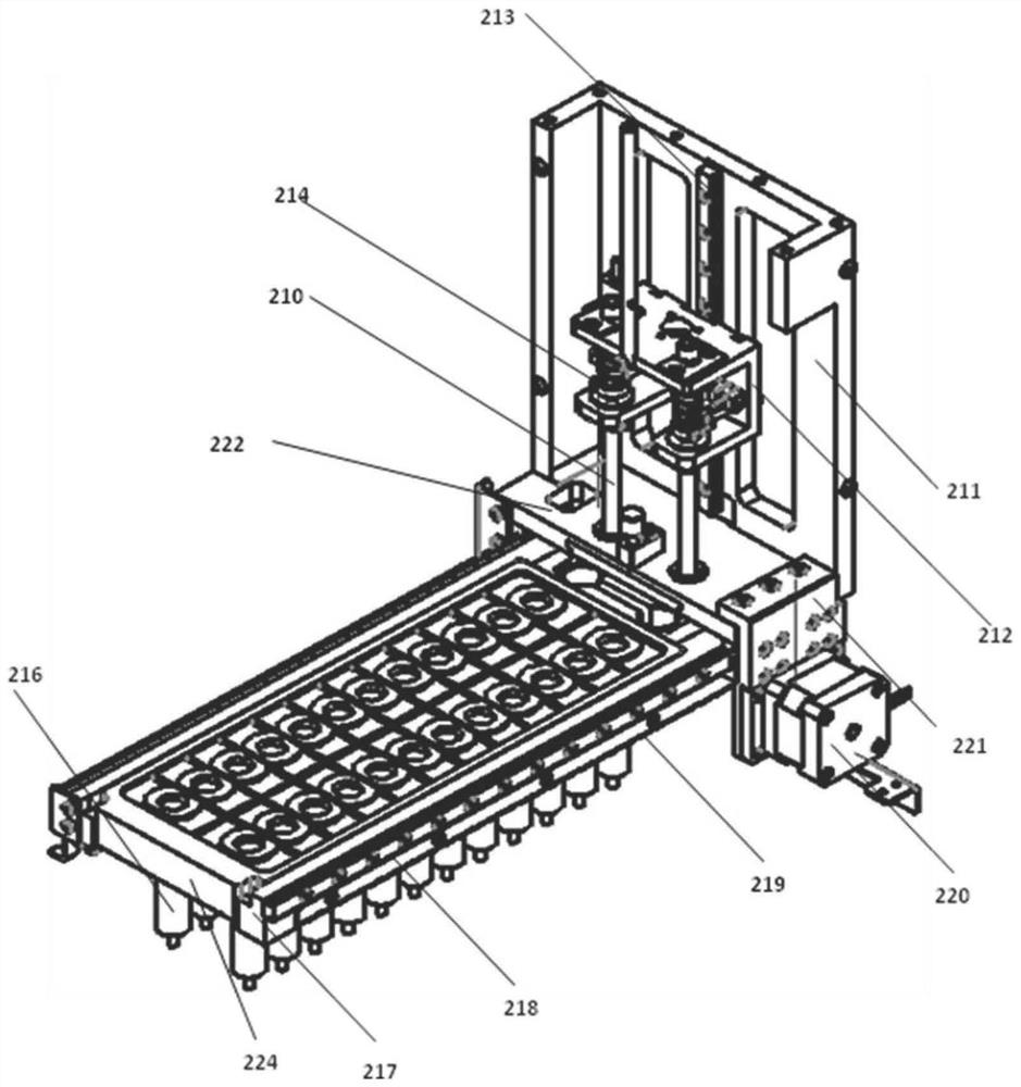
[0034] The invention relates to a nitrogen blowing component of a solid phase extraction nitrogen blowing concentrator, such as Figure 1-8As shown, it includes a bottom plate 8, a pillar 6, a base assembly 11, the base plate 8 is provided with the base assembly 11, the base assembly 11 is provided with a concentrated water tank assembly 5, and the concentrated water tank assembly 5 is provided above the Nitrogen blowing lifting assembly 3, the rear of nitrogen blowing lifting assembly 3 is provided with SPE column insert assembly 2, the right side of the nitrogen blowing lifting assembly 3 is provided with sample loading assembly 1, and the column 6 is 4, of which the left The lower ends of the two pillars 6 are vertically and fixedly connected to the bottom plate 8, and the lower ends of the two pillars 6 on the right side are fixedly connected to the upper guide rail mounting plate 111 of the sample loading needle. The sample loading assembly 1 includes the upper guide rail ...


PUM


Abstract

The invention relates to a nitrogen blowing assembly of a solid phase extraction nitrogen blowing concentrator, which comprises a nitrogen blowing needle guide rail mounting plate, a nitrogen blowing needle guide rail, a nitrogen blowing needle sliding block, a nitrogen blowing needle mounting plate, a nitrogen blowing needle assembly fixed plate, a nitrogen blowing needle, an air pipe joint, a battery valve support column, a battery valve support plate, a battery valve confluence plate, an electromagnetic valve and a nitrogen blowing needle lifting screw rod motor, the nitrogen blowing needle lifts the lead screw motor nut; wherein a T-shaped groove is formed in the nitrogen blowing needle assembly fixed plate, the T-shaped groove penetrates from the left side of the nitrogen blowing needle assembly fixed plate to the right side of the nitrogen blowing needle assembly fixed plate, the nitrogen blowing needle mounting plate is detachably clamped in the T-shaped groove, and the nitrogen blowing needle, the nitrogen blowing needle mounting plate and the electromagnetic group module form a module. The module can be detached from the nitrogen blowing lifting assembly, so that the module is convenient to replace; a plurality of electromagnetic valves are arranged on the electromagnetic valve confluence plate, and opening and closing of the electromagnetic valves can be selected according to working requirements so as to meet user requirements.

Description

technical field [0001] The invention belongs to the field of separation, and particularly designs a nitrogen blowing component of a solid phase extraction nitrogen blowing concentrator. Background technique [0002] Solid phase extraction is a sample pretreatment technology developed in recent years, which is mainly used for the separation, purification and enrichment of samples. [0003] The main purpose of solid-phase extraction is to reduce sample matrix interference and improve detection sensitivity. [0004] At present, solid-phase extraction instruments can complete the function of sample collection, but they cannot extract samples in large quantities. If the samples need to be processed in large quantities, repeated extractions are required, resulting in a tedious process and a waste of human and material resources. , it needs to be transferred to a special constant volume concentrator for constant volume concentration to suitable for subsequent analysis instruments....

Claims


Application Information

Patent Timeline
IPC IPC(8): G01N1/34G01N1/40G01F23/00B01D15/10
CPCG01N1/34G01N1/4022G01F23/00B01D15/10
Inventor 储涛徐玉卿
Owner 湖北鼎泰高科有限公司
Learn More