
Charging and discharging control method and energy storage system

A charge and discharge control and energy storage system technology, applied in control/regulation systems, collectors, electric vehicles, etc., can solve the problems of energy storage inverters that cannot match energy storage batteries and increase the use cost of energy storage systems.

Pending Publication Date: 2021-04-23
SUNGROW POWER SUPPLY CO LTD
View PDF4 Cites 2 Cited by
  • Summary
  • Abstract
  • Description
  • Claims
  • Application Information

AI Technical Summary

Problems solved by technology

[0003] With the development of energy storage battery technology, the voltage of energy storage batteries is getting higher and higher, and the iterative update of product specifications is accelerating. The voltage of many energy storage batteries exceeds the rated voltage range of the DC / DC converter in the energy storage inverter. In some household energy storage systems, in order to control the cost, the DC / DC converter in the energy storage inverter only has the function of boosting voltage, but not the function of stepping down. As a result, the energy storage inverter cannot match more For high-voltage energy storage batteries, when users replace energy storage batteries, they have to replace energy storage inverters that match higher voltages, which increases the cost of energy storage systems

Method used


Image

  • Charging and discharging control method and energy storage system
  • Charging and discharging control method and energy storage system
  • Charging and discharging control method and energy storage system

Examples


Embodiment Construction

[0050] The following will clearly and completely describe the technical solutions in the embodiments of the application with reference to the drawings in the embodiments of the application. Apparently, the described embodiments are only some of the embodiments of the application, not all of them. Based on the embodiments in this application, all other embodiments obtained by persons of ordinary skill in the art without creative efforts fall within the protection scope of this application.

[0051] The charging and discharging control method provided by the present invention is applied to an energy storage system equipped with an energy storage battery and an energy storage inverter. Specifically, it can be applied to the variable current controller in the energy storage inverter. Of course, it can also be applied to Other controllers in the energy storage system that can control the working status and conversion process of the DC / DC converter and DC / AC converter in the energy s...


PUM


Abstract

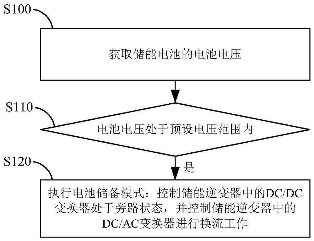
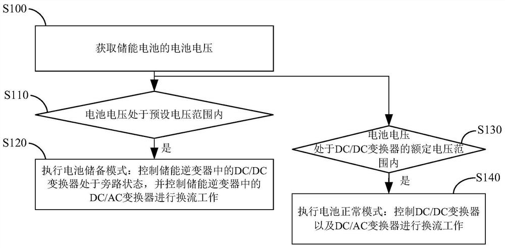
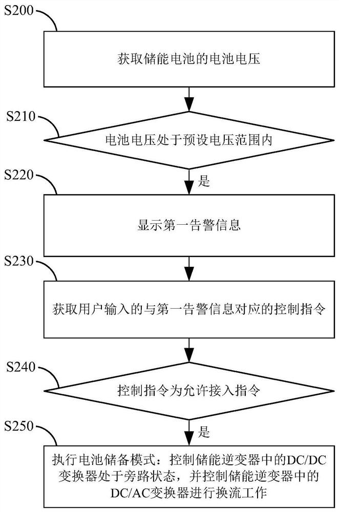
The invention provides a charging and discharging control method and an energy storage system, which are applied to the technical field of direct current energy storage. The method characterized in that a preset voltage range is set, the lower limit value of the preset voltage range is greater than the upper limit value of the rated voltage range of a DC / DC converter, and after the battery voltage of an energy storage battery is acquired, if the obtained battery voltage is within the preset voltage range, the following battery storage mode is executed: controlling a DC / DC converter in the energy storage inverter to be in a bypass state, and controlling a DC / AC converter in the energy storage inverter to perform current conversion work. According to the method, under the condition that the battery voltage is larger than the upper limit value of the rated voltage range of the DC / DC converter, the DC / DC converter is controlled to be in a bypass state, the DC / AC converter directly carries out current conversion work, limitation of the DC / DC converter is removed, and therefore the higher battery voltage is matched, and the use range of the energy storage inverter can be widened within a certain range.

Description

technical field [0001] The invention relates to the technical field of DC energy storage, in particular to a charging and discharging control method and an energy storage system. Background technique [0002] Household energy storage systems mostly include energy storage batteries and energy storage inverters, and the interior of the energy storage inverter is generally composed of DC / DC converters, DC / AC converters and converter controllers. The DC / DC converter and the DC / AC converter are connected in series, and the DC / AC converter is finally connected to the power grid or the load. The converter controller can collect the voltage information of the energy storage battery and control the work of the energy storage inverter. process. [0003] With the development of energy storage battery technology, the voltage of energy storage batteries is getting higher and higher, and the iterative update of product specifications is accelerating. The voltage of many energy storage ba...

Claims


Application Information

Patent Timeline
IPC IPC(8): H02J7/00H02J1/10H02M3/00H02M7/42
CPCH02J7/0068H02J7/0063H02J1/10H02J1/109H02M3/00H02M7/42H02J2207/20
Inventor 王新宇姜安营丁顺李晓迅张权宝
Owner SUNGROW POWER SUPPLY CO LTD
Learn More