
Pipe bending mechanism for hardware pipe machining and working method thereof

A technology for bending pipes and pipes, which is applied in the field of hardware pipe processing equipment, and can solve the problems of easy falling off, loose fixation, poor use safety effect, etc.

Inactive Publication Date: 2021-04-27
马鞍山天哲环保科技有限公司
View PDF0 Cites 2 Cited by
  • Summary
  • Abstract
  • Description
  • Claims
  • Application Information

AI Technical Summary

Problems solved by technology

[0002] Hardware pipes refer to the general term for building materials processed from gold, silver, copper, iron, and tin as raw materials; in daily life, hardware pipes are widely used; in the process of pipe processing, pipe bending mechanisms need to be used Bending the pipe material; the pipe bending mechanism in the prior art has a simple structure, and most of them are simple manual bending mechanisms, which are not fixed firmly and are prone to fall off during the bending process; at the same time, they cannot meet the needs of different lengths. At the same time, some electric equipment on the market has poor heat dissipation effect and poor safety effect. Therefore, it is necessary to design a bending mechanism and its working method for metal pipe processing.

Method used


Image

  • Pipe bending mechanism for hardware pipe machining and working method thereof
  • Pipe bending mechanism for hardware pipe machining and working method thereof
  • Pipe bending mechanism for hardware pipe machining and working method thereof

Examples


Embodiment approach

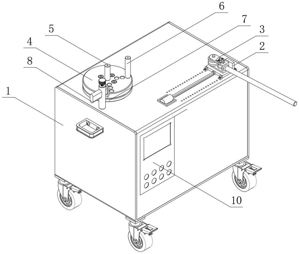
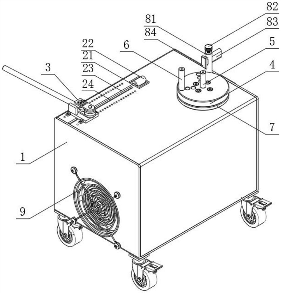
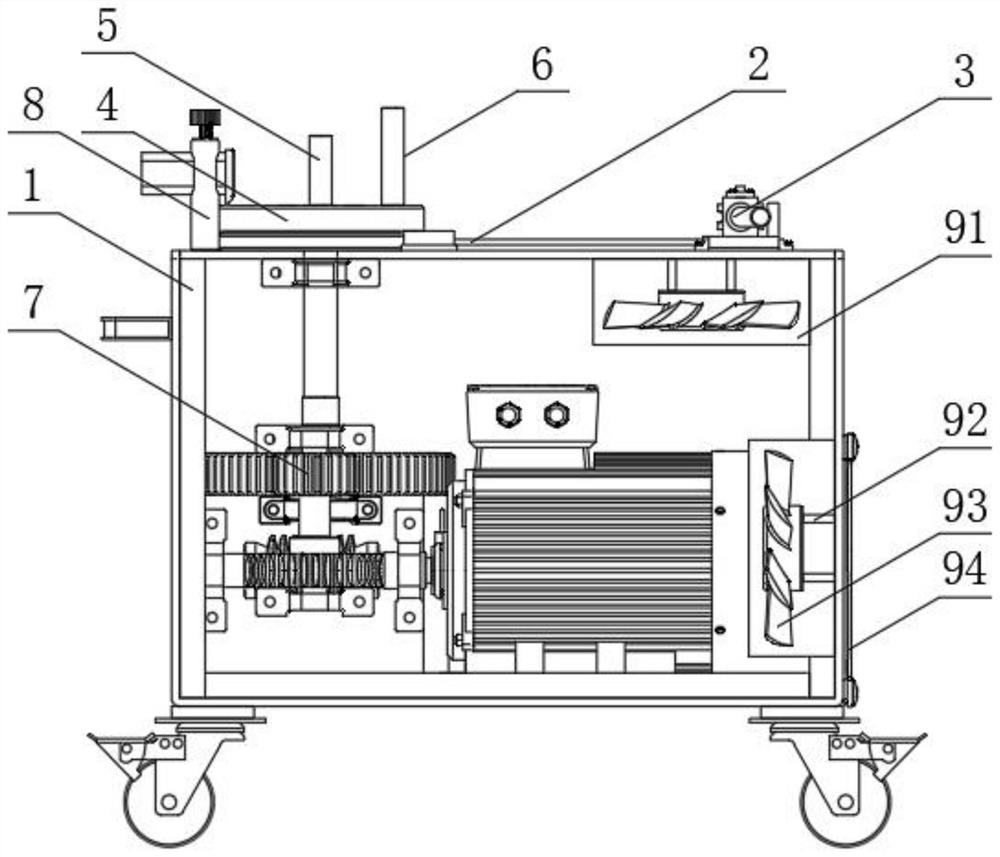
[0026]As an embodiment of the present invention, the displacement assembly 2 includes a fixing frame 21, an electric push rod 22, an extension rod 23, a guide slide 24, and a fastening seat 25, and the fastener 21 is fixedly mounted on the top end of the chassis 1. On one side, the upper surface of the fixing frame 21 is fixedly mounted with the electric push rod 22 by a screw, and one end of the electric push rod 22 is attached to the mounting rod 23, and the other end of the extension rod 23 is connected to the fastening seat 25, and the fastening seat One end of 25 is fixed to the adjustment bottom plate 39, and the guide chute 24 is opened on the top surface side of the chassis 1, and the guide slider 310 is inserted inside the guide slot 24, and it is easy to adjust the position of the adjustment the bottom plate 39, thereby Convenient for pipe for different lengths.

[0027]As an embodiment of the present invention, the upper end surface of the chassis 1 is located on both sides ...


PUM


Abstract

The invention discloses a pipe bending mechanism for hardware pipe machining and a working method thereof. The pipe bending mechanism comprises a case, a displacement assembly, a limiting assembly, a pipe bending rotary disc, a first bent pipe, a second bent pipe, a power assembly, a supporting assembly, a heat dissipation assembly and an electric control plate, wherein the pipe bending rotary disc is mounted on the top end face of the case; the first bent pipe is inserted into the center of the end face of the pipe bending rotary disc; the second bent pipe is inserted into the outer side of the end face of the pipe bending rotary disc; the power assembly is arranged below the bottom end face of the pipe bending rotary disc and installed at the bottom of the inner side of the case; and the limiting assembly is arranged on one side of the outer portion of the pipe bending rotary disc. The pipe bending mechanism is small in size and convenient to move; the pipe bending mechanism can bend pipes of different models and lengths, has a good limiting and fixing effect on the pipes, and is firm in fixation and good in bending effect; and meanwhile, a good heat dissipation effect is achieved, and the heat dissipation rate of a motor can be effectively increased.

Description

Technical field[0001]The present invention relates to the field of hardware tube processing equipment, and is specifically used for eluting mechanism for hardware pipe processing and its working methods.Background technique[0002]Hardware pipe, finger, silver, copper, iron, and Tin five metal materials are generally referred to in the construction materials obtained by the raw materials; in daily life, the hardware pipe is widely used; the pipe is used in the process of processing, need to be used to bending mechanism Bending the pipe; the elongation mechanism in the prior art, the structure is simple, mostly a simple manual bending mechanism, fixed, and is easy to fall off during bending; at the same time, different lengths cannot be met The diameter pipe is bent; at the same time, the heat dissipation effect of some electric equipment on the market is poor, and the safety effect is not good. Therefore, it is necessary to design a bending mechanism for hardware pipe processing and i...

Claims


Application Information

Patent Timeline
IPC IPC(8): B21D7/024B21D7/16B21D43/00
CPCB21D7/024B21D7/16B21D7/165B21D43/003
Inventor 范士金游登洲沈玉鹏刘成
Owner 马鞍山天哲环保科技有限公司
Learn More