
Eureka
For R&D, Eureka makes reading and utilizing patents & technical documents easy.
Eureka AIR
Designed for self-driven R&D workflows. Generate viable solutions, solve complex R&D challenges, empower your innovation with AI.

Eureka Materials
Designed for material experts only. Revolutionize your material R&D, from search, analyze, to developing new materials.

TechResearch
Generate reliable direction feasibility study reports for your R&D in just a few steps.

TechSeek
Discover and master advanced knowledge NOW. Basics, ideas, possibilities, all at once.

TechMind
As an expert in R&D Theories, TechMind can generates customized viable solutions instantly.

TechRisk
Analyze your overall solution with one click, know your potential R&D risks in advance.

TechMonitor
Get weekly tech updates, stay abreast of the latest tech innovations and key insights.
Full-automatic kitchen knife sharpening machine
A fully automatic, kitchen knife technology, applied in the direction of grinding frame, grinding machine parts, grinding bed, etc., can solve the problems of low safety factor, time-consuming and labor-intensive, etc., and achieve the effect of reducing heat
- Summary
- Abstract
- Description
- Claims
- Application Information
AI Technical Summary
Problems solved by technology
Method used
Image

Examples
Embodiment 1
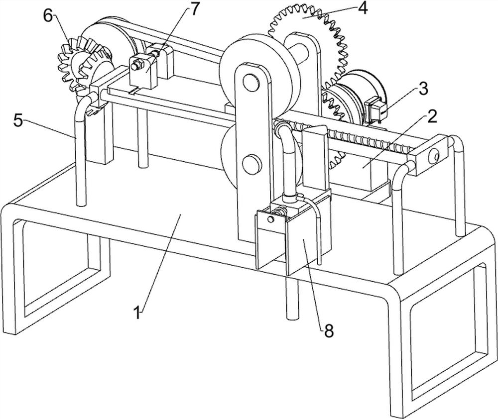
[0026] A fully automatic kitchen knife sharpening machine, such as figure 1 As shown, it includes a bed 1, a motor frame 2, a geared motor 3, a grinding assembly 4, and a support frame 5. The right wall of the rear part of the bed 1 is provided with a motor frame 2, and a geared motor 3 is installed on the motor frame 2. 1 is provided with a grinding assembly 4 on the right side of the upper front part, and the grinding assembly 4 is connected with the output shaft of the reduction motor 3, and the bed 1 is provided with a support frame 5.
[0027] When people need to polish kitchen knives, they can use this kitchen knife sharpening machine. First, the kitchen knife to be polished is placed on the grinding assembly 4, then the reduction motor 3 is started, and the output shaft of the reduction motor 3 rotates to drive the grinding assembly 4 to grind the kitchen knife. Close reduction motor 3 when polishing is finished, thereby polishing assembly 4 stops operation, then takes ...
Embodiment 2
[0029] On the basis of Example 1, such as figure 2 As shown, the grinding assembly 4 includes a first support plate 41, a first rotating shaft 42, a first spur gear 43, a first grinding wheel 44, a second rotating shaft 45, a second spur gear 46 and a second grinding wheel 47, on the bed 1 The first supporting plate 41 is arranged on the front and rear of the right side, and the first rotating shaft 42 is arranged in a rotating manner between the two first supporting plates 41 middle parts. The first spur gear 43 is arranged on the top, the first grinding wheel 44 is arranged on the front part of the first rotating shaft 42, the second rotating shaft 45 is arranged in a rotating manner between the tops of the two first supporting plates 41, and the second rotating shaft 45 is arranged on the rear part of the second rotating shaft 45. Two spur gears 46, the second spur gear 46 meshes with the first spur gear 43, the second rotating shaft 45 front portion is provided with a sec...
Embodiment 3
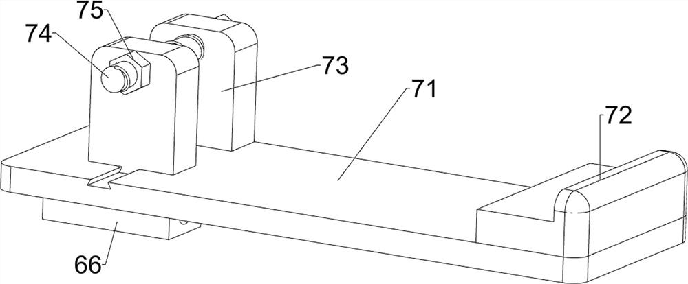
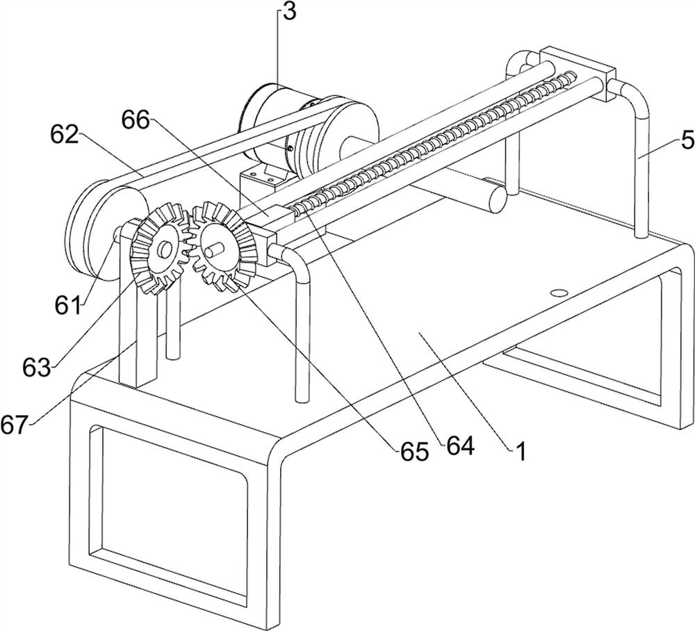
[0032] On the basis of Example 2, such as image 3 , Figure 4 with Figure 5 As shown, it also includes a feeding assembly 6, the upper left part of the bed 1 is provided with a feeding assembly 6, the feeding assembly 6 is connected with the output shaft of the reduction motor 3 and the support frame 5, the feeding assembly 6 includes a third rotating shaft 61, a transmission Component 62, first bevel gear 63, screw rod 64, second bevel gear 65, first slide block 66 and second support plate 67, bed 1 upper left part rear side is provided with second support plate 67, second support plate 67 upper rotation type is provided with the 3rd rotating shaft 61, is connected with the transmission assembly 62 between the 3rd rotating shaft 61 rear parts and the reduction motor 3 output shafts, the 3rd rotating shaft 61 front parts are provided with the first bevel gear 63, the support frame 5 top inner The rotary type is provided with a screw rod 64, the left part of the screw rod 6...
PUM
 Abstract
Description
Claims
Application Information
 - R&D Engineer
- R&D Manager
- IP Professional
- Industry Leading Data Capabilities
- Powerful AI technology
- Patent DNA Extraction
Browse by: Latest US Patents, China's latest patents, Technical Efficacy Thesaurus, Application Domain, Technology Topic, Popular Technical Reports.
© 2024 PatSnap. All rights reserved.Legal|Privacy policy|Modern Slavery Act Transparency Statement|Sitemap|About US| Contact US: help@patsnap.com