Computer big data image processing equipment

An image processing device and big data technology, applied in the field of image processing, can solve the problems of low efficiency of artificial paint, poor quality of printing effect, inconvenient printing on high walls, etc.

Active Publication Date: 2021-04-27
UNIV FOR SCI & TECH ZHENGZHOU
View PDF5 Cites 0 Cited by
  • Summary
  • Abstract
  • Description
  • Claims
  • Application Information

AI Technical Summary

Problems solved by technology

[0008] In view of the above situation, in order to overcome the defects of the prior art, the present invention provides a computer big data image processing equipment, which effectively solves the problems of the...

Method used


Image

  • Computer big data image processing equipment
  • Computer big data image processing equipment
  • Computer big data image processing equipment

Examples


Embodiment 1

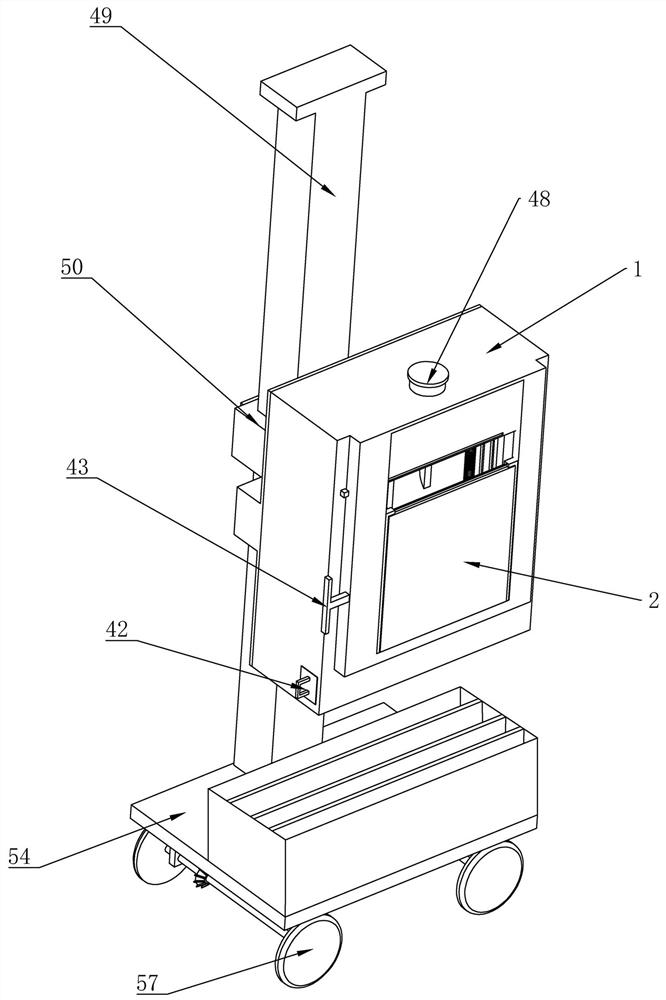
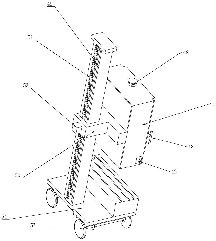
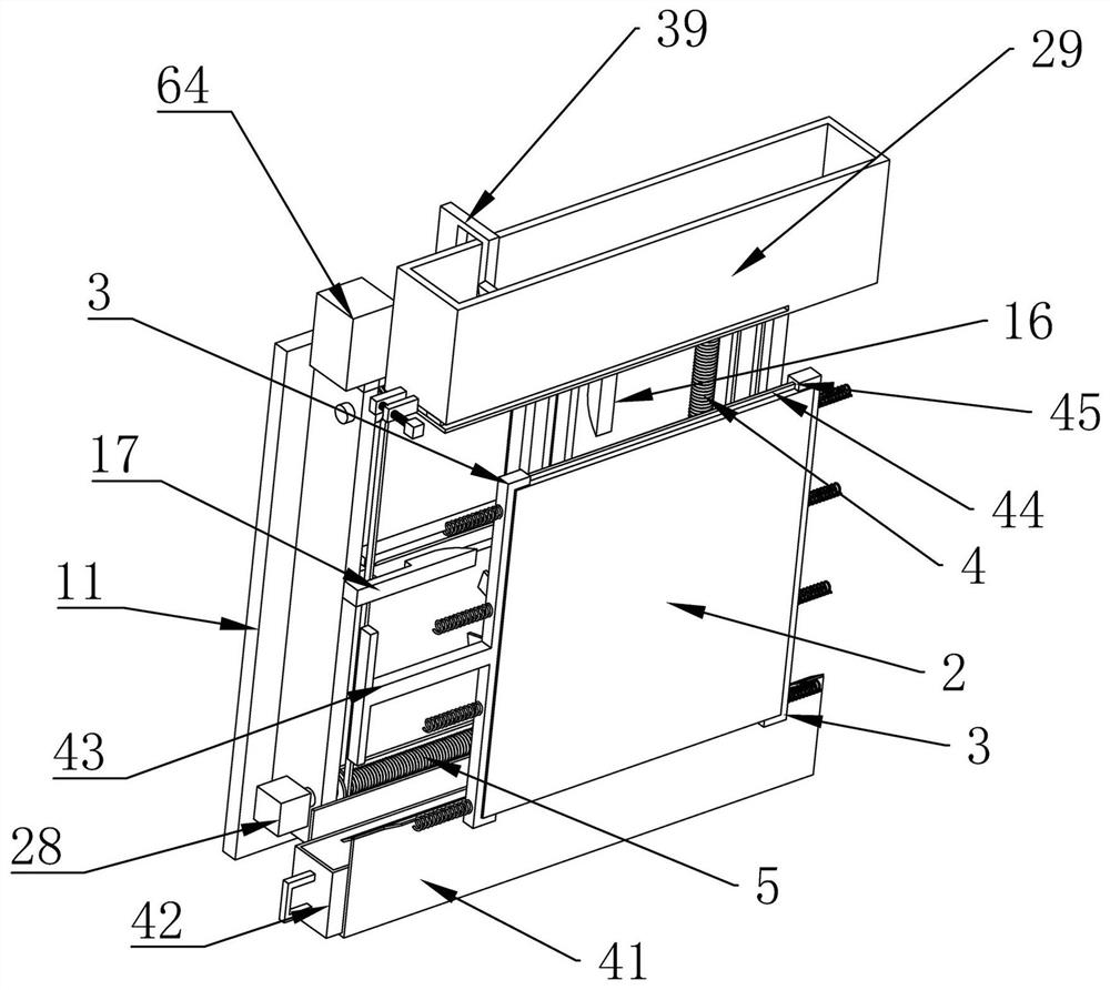
[0048] Embodiment 1, the present invention is computer big data image processing equipment, which is characterized in that it includes a printing cabinet 1, and a silk screen board 2 is slidably connected to one side of the printing cabinet 1, and the screen board 2 is detachably connected to the printing cabinet 1 In addition, the screen board 2 can be freely replaced according to customer needs to realize printing of different patterns. The two sides of the screen board 2 are contacted and connected with a fixed frame 3 slidingly connected to the printing cabinet 1. The fixed frame 3 The screen board 2 can be fixed, and the screen board 2 can be taken out and put in by pulling the fixing frames 3 on both sides and the screen board 2 can be fixed. The inner walls of the left and right sides of the printing cabinet 1 are rotated and connected with lifting Reciprocating screw rod 4, the upper and lower ends of the printing cabinet 1 are rotatably connected with translational rec...

Embodiment 2

[0052] Embodiment 2, on the basis of Embodiment 1, the end of the upper scraper 9 and the lower scraper 10 away from the screen plate 2 are provided with jacking grooves 15, and the upper and lower ends of the printing cabinet 1 are All are fixedly connected with the first stop rod 16, and the left and right sides of the described printing frame are all fixedly connected with the second stop rod 17, and the described first stop rod 16 and the described second stop rod 17 are all fixedly connected with each other. Slidingly connected in the jacking groove 15, when the first limiting rod 16 and the second limiting rod 17 touch the jacking groove 15, the upper scraper 9 or the lower scraper 10 will be lifted up, and the paint will be pushed along the The screen plate 2 flows out to prepare for the next coating. By setting a gap on the side of the jacking groove 15 that allows the first stop bar 16 and the second stop bar 17 to pass through, it can be ensured that when the printing...

Embodiment 3

[0056] Embodiment three, on the basis of embodiment two, the top of the screen plate 2 is provided with a feed tank 29 fixedly connected to the printing cabinet 1, the feed tank 29 is filled with paint, and the The bottom of the feeding trough 29 is provided with a feeding port 30, and the feeding port 30 is located above the upper scraper 9. When the paint flows out along the feeding port 30, the paint can fall on the upper scraper 9 without falling out of the upper scraper. Plate 9, the described feeding port 30 is provided with a quantitative plate 31 that is slidably connected in the feeding chute 29, the sliding of the quantitative plate 31 can control the opening size of the feeding port 30, and one side of the quantitative plate 31 is rotatably connected There is an adjusting screw 32, and one side of the feeding chute 29 is fixedly connected with an adjusting fixing plate 33, and the adjusting screw 32 runs through the adjusting fixing plate 33 and is threadedly matched...


PUM


Abstract

The invention relates to computer big data image processing equipment. The problems that an existing device cannot achieve automatic feeding, the manual coating efficiency is low, and the manual operation printing effect and quality are poor are effectively solved. According to the technical scheme, the computer big data image processing equipment comprises a printing cabinet, wherein a silk screen plate is arranged on the printing cabinet; a fixing frame is arranged on the silk screen plate; lifting reciprocating lead screws are arranged on the printing cabinet; the printing cabinet is rotationally connected with translation reciprocating lead screws; a lifting rod is slidably connected between the two lifting reciprocating lead screws; a translation rod is slidably connected between the two translation reciprocating lead screws; a printing frame is arranged on one side of the silk screen plate; and an upper scraper and a lower scraper are slidably connected to one side of the printing frame and are in contact connection with the silk screen plate. According to the computer big data image processing equipment provided by the invention, by arranging the sliding printing frame, paint is evenly smeared; by arranging a discharging groove, automatic feeding is achieved; and the diversity of screen printing patterns is adjusted through the detachably-connected silk screen plate, so that more selection space is provided for customers, and high universality and practicability are achieved.

Description

technical field [0001] The invention relates to the technical field of image processing, in particular to computer big data image processing equipment. Background technique [0002] Images are the main source of information for human beings to obtain and exchange. Therefore, the application field of image processing must involve all aspects of human life and work. Computer image processing is closely related to the development of technologies such as computers, multimedia, intelligent robots, and expert systems. With the continuous expansion of the scope of human activities, the application field of image processing will also continue to expand; [0003] With the continuous improvement of living standards, people are more pursuing high-quality life, involving various fields of clothing, food, housing and transportation, and the application of image processing is also widely used with the improvement of people's quality of life. Interior decoration is one of them. When perfo...

Claims


Application Information

Patent Timeline
IPC IPC(8): B41F15/08B41F15/46B41F33/16
CPCB41F15/08B41F15/46B41F33/16
Inventor 王玉萍于海燕易伟曾毅
Owner UNIV FOR SCI & TECH ZHENGZHOU
Why Eureka
Try Eureka